The initial unprocessed raw point cloud from the scan is a collection of individual data sets or frames. It must be fused, meshed and textured (optional) to make it a high-quality 3D model. This can be done by using either One-click edit or manually editing the raw data.
¶ One-click Edit
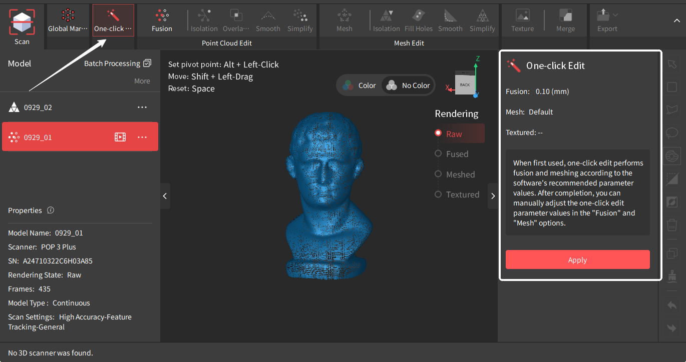
Revo Scan 5 has a powerful one-click processing feature that automatically performs fusion, meshing, and texturing (if a color scan was done) based on the best detected setting for the point cloud.
Note: For new users, the “One-click Edit” function is recommended for the first few scans.
Tap the “Apply” button to perform the “One-click Edit” function. Click the “Cancel” button to cancel the process.
¶ Manual Edit
In manual editing, you can fully edit your raw point cloud data during every step of the process or edit imported 3D models from other sources.
¶ Point Cloud Edit
¶ Fusion
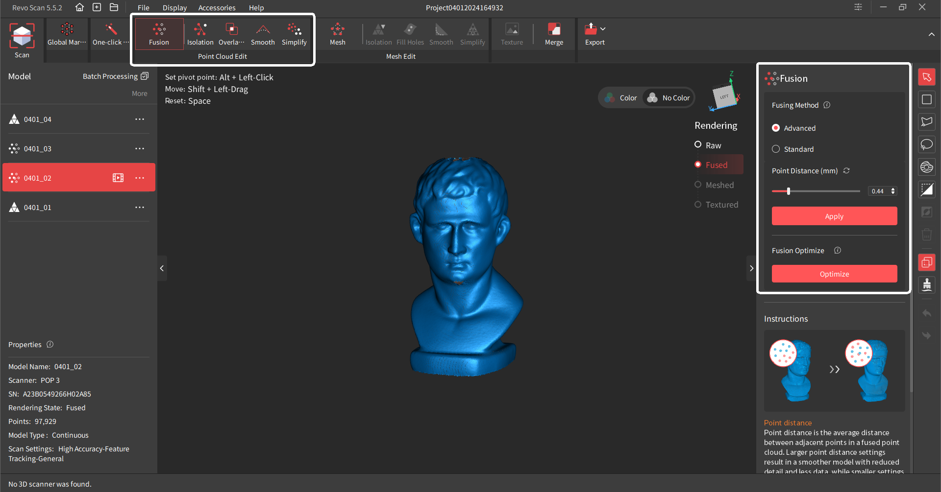
Fusion is fusing the raw scan data captured by the scanner into a unified point cloud model. There are two fusion methods:
• Standard Fusion: It processes data fast and is better for processing large data scans with many frames.
• Advanced Fusion: It produces a high-quality point cloud but spends more time. It is suitable for scans with high detail requirements.
Point Distance: The average distance between the adjacent points in a fused model. Revo Scan will suggest an optimal point distance for each scan, but different values can be specified depending on your requirements.
Despite having a higher minimum point distance than Standard Fusion, advanced Fusion will produce a more detailed model due to more advanced algorithms.
Fusion Optimize: For objects with geometric features, detail performance can be significantly enhanced through fusion optimization. If you need to undo the optimization, click the undo button in the bottom right corner.
Tap the “Apply” button to perform the Fusion function and click the “Cancel” button to cancel it.
¶ Point Cloud Isolation
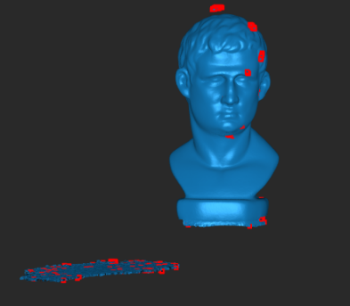 |
Detects and removes the isolated point cloud data disconnected from the main point cloud model (see the red area in the figure). Isolation Rate: The percentage of points within isolated point clouds relative to the total number of points. Setting a higher rate will detect more isolated point clouds. |
¶ Point Cloud Overlap Detection
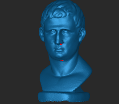 |
Identifies and deletes overlapping data in the point cloud for a more consistent model. It can be used repeatedly to simplify point cloud data. Vertical Distance: The distance between the overlapped point cloud noise and the captured surface area. If it's less than the set value, it's considered noise and removed. If it exceeds the set value, it's not removed. |
¶ Point Cloud Smooth
Removes noise from the point cloud to make it smoother.
To use it, select its strength and the number of times it applies smoothing consecutively.
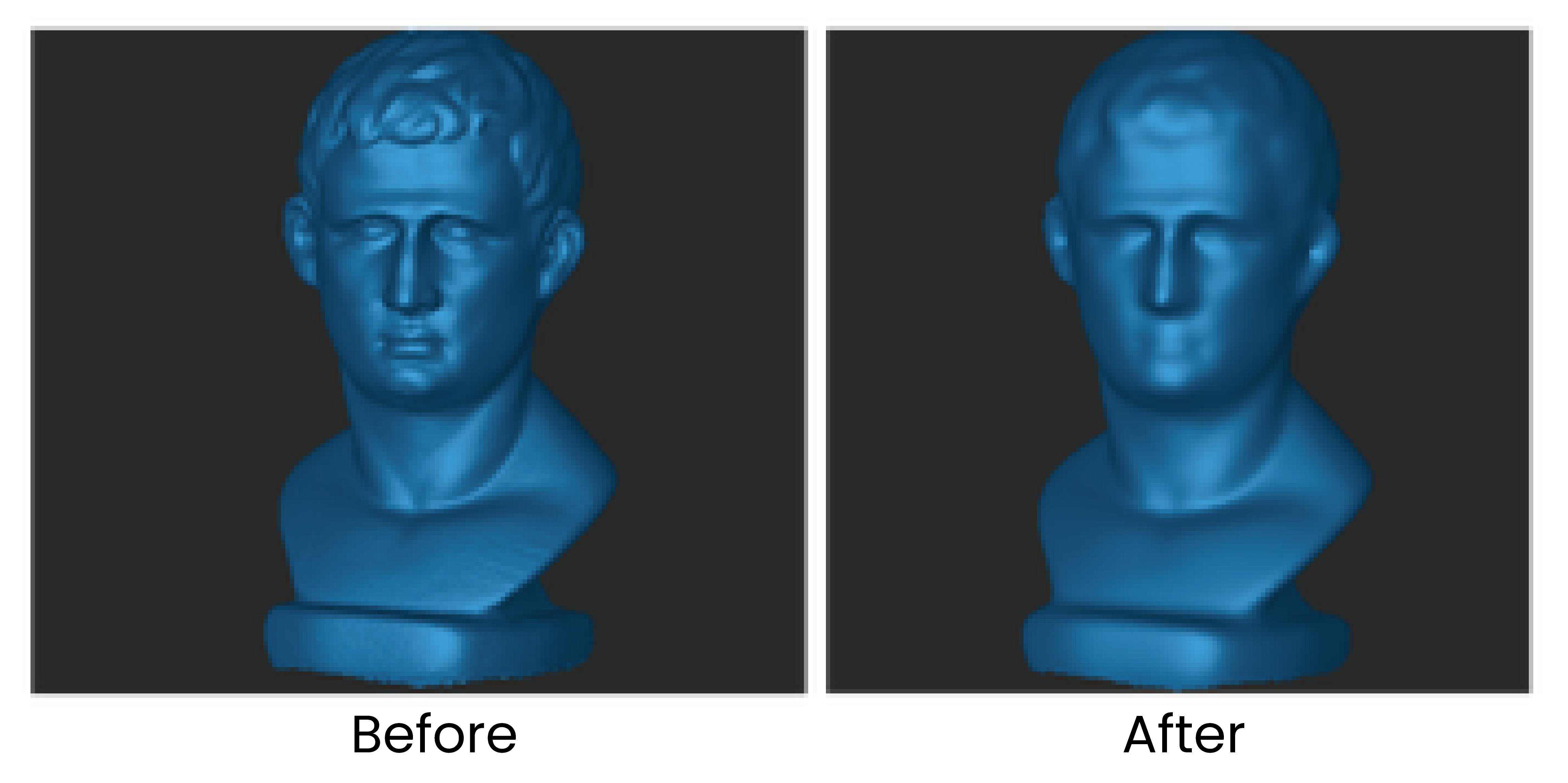
For feature-rich models, excessive smoothing may result in loss of details (see the figure below).
¶ Point Cloud Simplify
Reduces the density of the point cloud and the amount of data for more manageable processing, storage and sharing. There are two different downsampling methods:
• Uniform: Removes the set percentage of points across the model evenly.
• Geometric: Intelligently identifies flat or plain surfaces in the point cloud and will remove the set percentage of points from these areas while leaving more complex areas alone to maintain the details.
Ratio: The percentage of simplified point cloud data to the total amount of data. Setting a higher ratio will delete more point cloud data from the model.
Note: Selecting a ratio that is too large may impact the model's quality.

¶ Mesh Edit
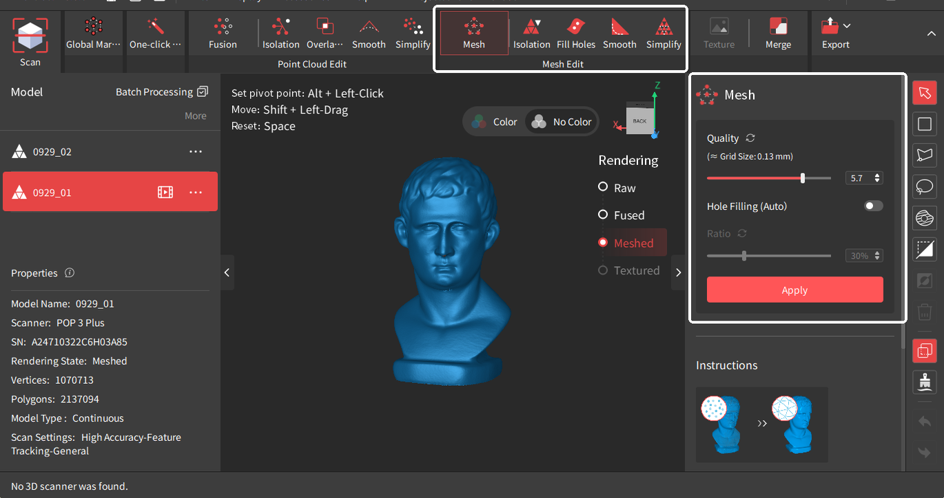
Mesh is created by constructing triangles from the points in the point cloud to create a solid surface. Before being used in most 3D modeling or slicing software, the point cloud must be meshed.
• Quality: The mesh model’s density and level of detail. Setting a higher value results in a denser and more detailed mesh model but spends more time.
• Hole Filling (Auto): Revo Scan automatically identifies and fills all the holes on the mesh model.
• Ratio: The percentage of the hole diameter to the overall mesh size. The holes smaller than this ratio will be filled.
Note: The auto Hole Filling function applies to small holes. It’s suggested to use the Fill Holes tool in the mesh editing tab to fill larger holes.
Tap the “Apply” button to perform the Mesh function.
¶ Mesh Isolation
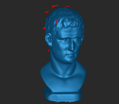 |
Detects and removes the isolated mesh data disconnected from the main mesh. Isolation Rate: The percentage of an isolated mesh relative to the total number of meshes. Setting a higher value will detect more isolated mesh data. |
¶ Fill Holes
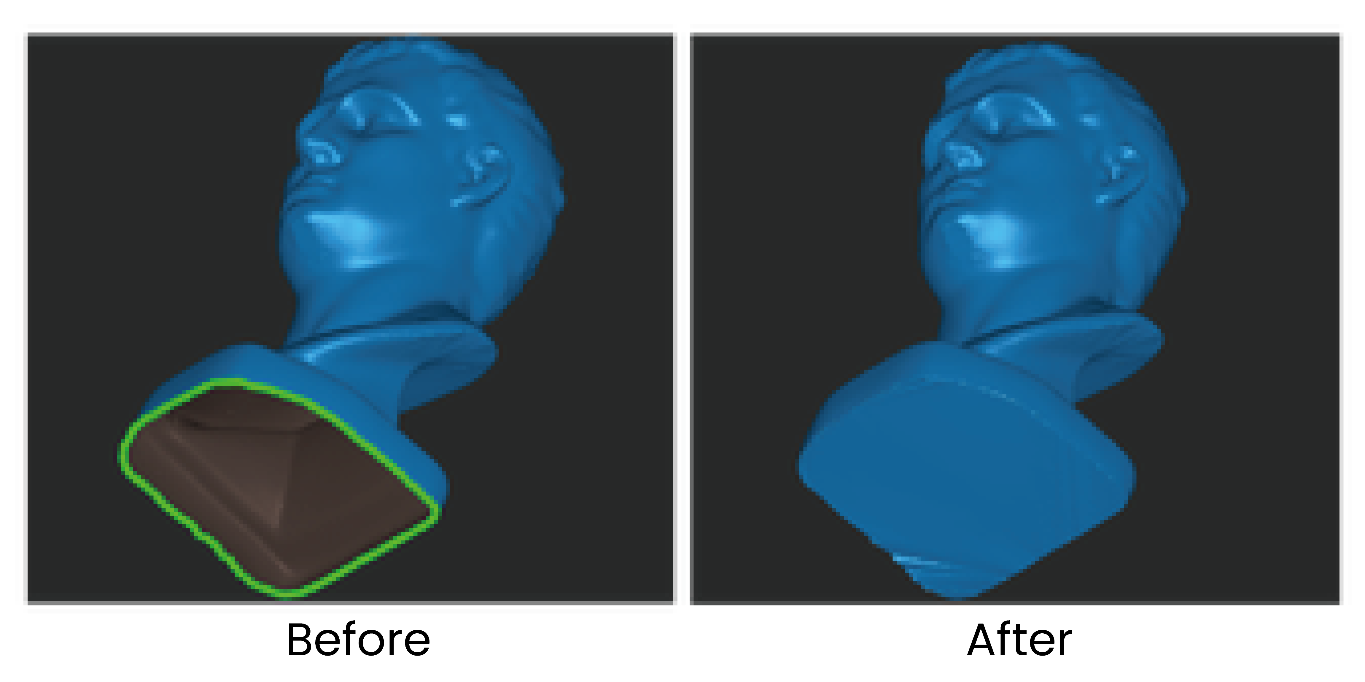
Detects all holes on the model’s surface. Select the holes and fill them with a Plane or Curved surface.
¶ Mesh Smooth
Removes noise from the mesh model to make it smoother.
To use it, select its strength and the number of times it applies smoothing consecutively.
¶ Mesh Simplify
Reduces the amount of mesh data in the model for more manageable processing, storage and sharing.
Ratio: The percentage of simplified mesh data to the total data volume. Setting a higher ratio will remove more details, resulting in a smaller file size.

¶ Texture
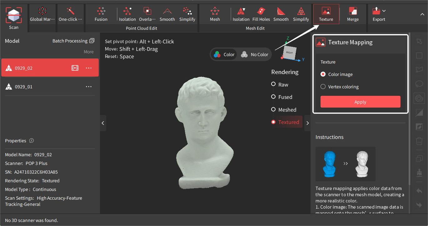
Texture is applying the color data captured by the RGB camera to the mesh to create a high-quality colored 3D model. There are two texturing methods:
• Color Image
This method maps the image data captured by the scanner's RGB Camera on the mesh’s surface to create a colored model.
• Vertex Coloring
This method generates textures from the mesh's vertices color.
Click the “Apply” button to perform the “Texture” function and click the “Cancel” button to cancel the process.
¶ Model Merging
The merging function supports the alignment of multiple scans in a project into a new model. Please note that the scans can only be merged after they are fused. There are two alignment methods: Feature and Manual Alignment.
¶ Feature Alignment

Select the models, and Revo Scan will automatically merge them by identifying and aligning the overlapping features in multiple models. The overlapping area between any two models should be more than 10% (for best results, 40% to 50% is recommended). Up to 9 fused models can be selected and merged simultaneously.
¶ Manual Alignment
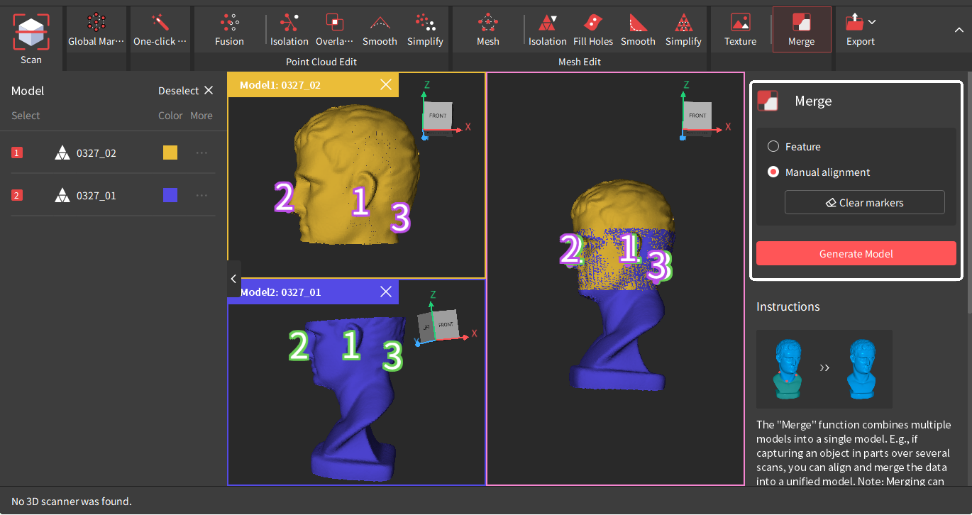
At least 3 reference points must be manually placed in matching locations on each model. Then, Revo Scan merges the two models by identifying and aligning the reference points. Only 2 models can be merged at a time.
• The number of corresponding reference points on both models must be the same.
• Avoid grouping the markers together in a small area.
• Zoom in on the features of each model to place the marker points carefully.
¶ Key Frames Edit
Use it to edit or delete the raw data before fusion. This tool can be used to go through captured point cloud data frame-by-frame and quickly find the misaligned or faulty frame for deletion.
Key Frames Edit Tutorial Video
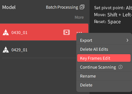 |
Go to the project panel and click the  icon or click the icon or click the  icon > Key Frames Edit to enter the Key Frames Edit interface. There are two methods to edit the key frames: icon > Key Frames Edit to enter the Key Frames Edit interface. There are two methods to edit the key frames: |
1) Click the  button to autoplay through the frames individually. Then, select any unwanted frames and click the
  button next to each frame’s name.
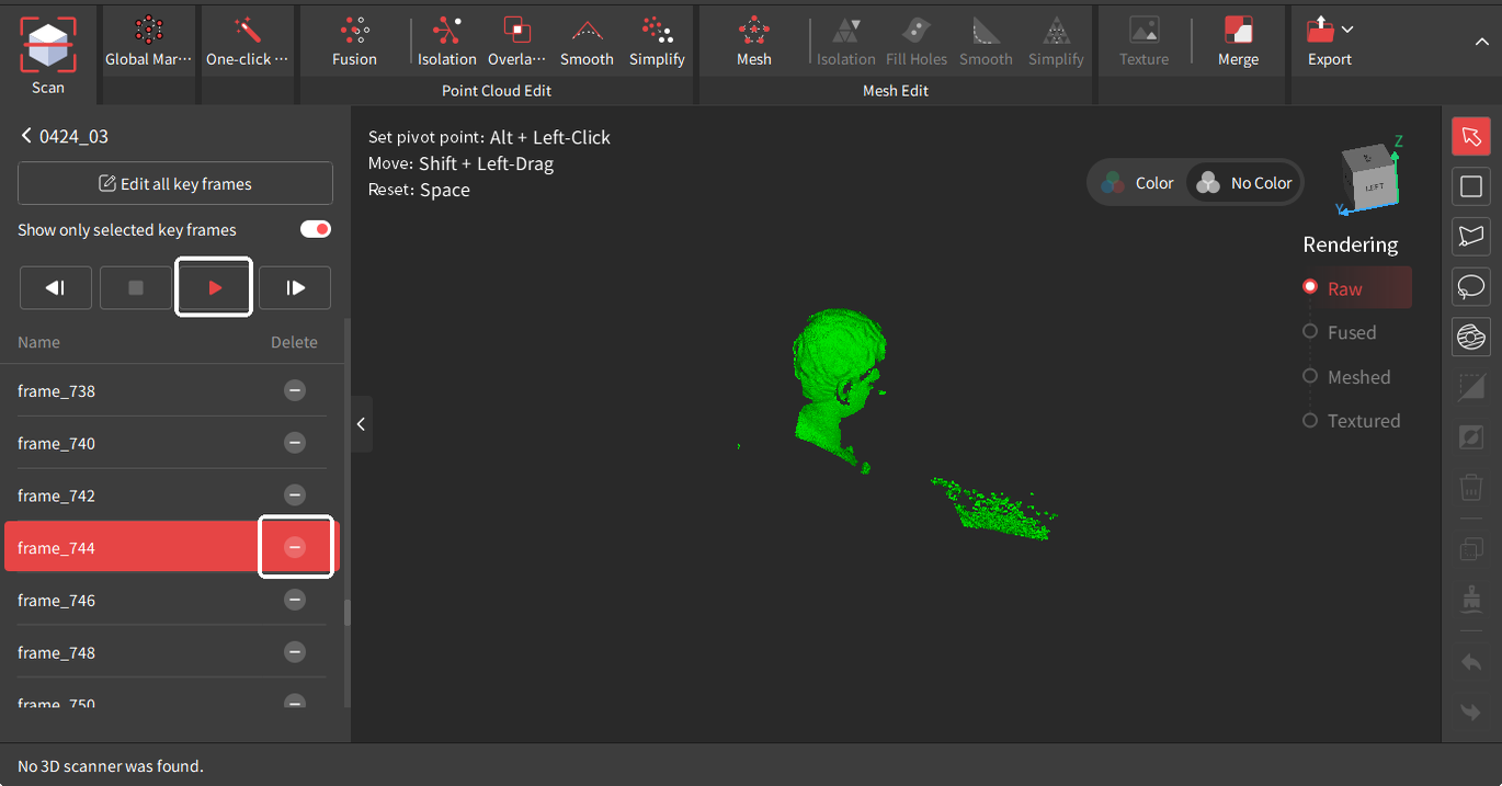
2) Enter the Key Frames Edit interface and use a selection tool from the Tool Bar to select unwanted data. The frames with the data will be automatically selected. Click the  button to delete the unwanted data in the selected frames or the
  button to delete all selected frames.

¶ Tool Bar
The Tool Bar provides multiple tools that enable users to select unwanted local data for detailed editing or deletion manually.
Note: The Tool Bar can’t be used for raw data or textured models.
 |
Orbit Rotate the view in any direction. Clicking it will also de-select any previously selected areas. |
 |
Rectangular Selection Click and hold the left mouse button to draw a rectangle around any point on the model to select that area. |
 |
Polygon Selection Left-click to create anchor points to select a mesh's polygons (faces). The Polygon tool creates a straight line between each Anchor Point. Click on any edge of the area to be selected and release the mouse pointer to make an Anchor Point. |
 |
Lasso Selection Click and hold the left mouse button, then draw a shape around an area to select it. Release the mouse button, and the selection will be closed by connecting the current pointer location to the start location with a line. |
 |
Select Connection Left-click on a point or a data area, and the tool will automatically select the adjacent or connected points or areas. |
 |
Clip Position the cursor, click and hold the left mouse button, and drag. The clipping plane will appear as a line with an arrow. The portion of the model in the direction of the line’s arrow will be selected. Press <Delete> to apply the change, <Esc> to cancel. |
 |
Invert Selection Use the invert selection button to change the selected area from the currently selected area to anything that wasn’t selected. |
 |
Delete Click to remove the selected data. Alternatively, use your keyboard’s delete button. |
 |
Select Through Used with Polygon Selection, Lasso Selection, etc. Enable it to select data right through the model. |
 |
Smooth Brush Place the cursor over a rough area (e.g., marker holes), then left-click or left-click and drag to smooth. |
 |
Undo Use to remove the scan data or revert the changes made to the model. |
 |
Redo Use to add back the scan data or the changes made to the model. |