¶ 1. About This Manual
Welcome to the Revopoint 3D scanner user manual! This manual provides operating instructions for the POP 4. Please read the manual before your first use to ensure you use this scanner correctly and safely. If needed, you can click on any topic in the navigation bar to quickly jump to that section.
Manual Download
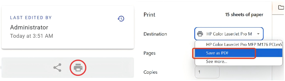
If you need a PDF manual, click the Print Format button at the bottom of the navigation bar on the left side of the manual, and select "Save as PDF" from the options.
¶ 1.1 Read Before Using
- This manual is specifically for POP 4 3D Scanner and guides users through setup, connection, scanner calibration, and initial scanning, helping them operate the product correctly and efficiently and achieve optimal scanning performance.
- This manual is frequently updated to cover the product's latest features and improvements.
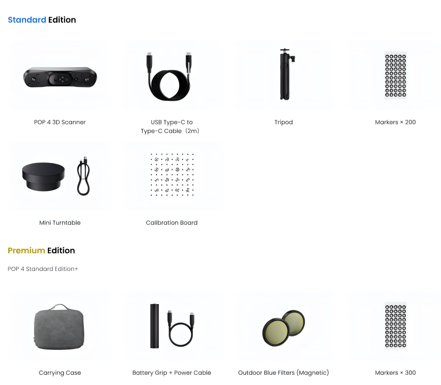
- Verify that all components in your box are complete and undamaged before first use.
¶ 1.2 Warnings
- This product uses a Class 1 laser projector. Avoid looking directly at it at close range! Please refer to the Class 1 laser standard document for details. To prevent laser reflection, avoid placing reflective surfaces like mirrors or glass in the path of the laser beam.
- Please keep the scanner away from water and other liquids, and avoid dropping or bashing it.
- This product's operating environment temperature range is 0°C to 40°C (32°F to 104°F). Please use the product only within this range.
- Do not remove, disassemble, or modify any part of the product. Any modifications to the product may render it non-compliant with safety standards.
- Keep this product out of the reach of children.
¶ 1.3 Online Resources



¶ 2. About the Product
¶ 2.1 Product Introduction
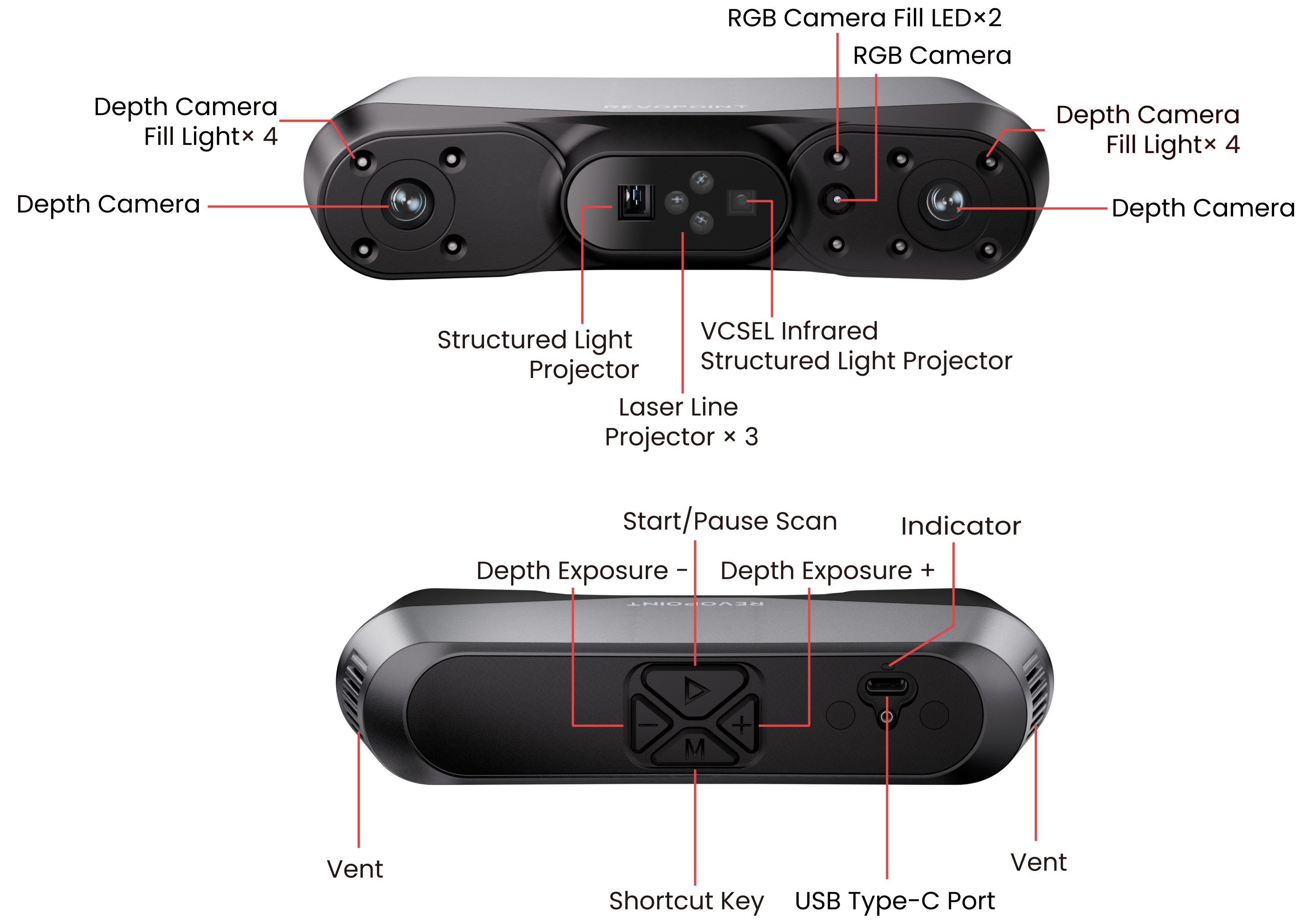
The POP 4 is a portable 3D scanner that supports both blue-light and near-infrared scanning. It offers multiple scanning modes, including Cross/Single Laser Lines, Full-Field Structured Light, VCSEL Structured Light, and Hybrid Structured Light, making it suitable for challenging scanning scenarios such as highly reflective surfaces, deep holes, and outdoor environments under strong sunlight.
¶ 2.2 What's in the Box
¶ 2.3 Product Profile
¶ 3. Software Download and Usage
The POP 4 scanner must be used with the Revo Scan 6 (Computer) or Revo Scan 6 (Mobile) software. Before use, please download and install the software.
|
Software |
Revo Scan 6 (Computer) |
Revo Scan 6 (Mobile) |
|
Download Channel |
or Mobile app store |
|
|
Software Requirements |
Minimum PC Requirements: Windows: Win 10/11 (64 bit)
macOS: macOS 11.0 or better
Recommended PC Requirements: Windows: Win 10/11 (64 bit)
macOS: macOS 11.0 or better
|
Mobile Requirements (The iOS version of Revo Scan 6 is coming soon): Android:
iPhone: Models after iPhone X
iPad: 10th Gen iPad or later |
¶ 3.2 Platform and Feature Compatibility
| Platform & System | Have Software | Laser-Line GPU Acceleration | AI Intelligent Segmentation | 3DGS |
|---|---|---|---|---|
| Windows-NVIDIA | ✓ | ✓ | ✓ | ✓ |
| Windows-AMD | ✓ | ✓ | ✓ | ✓ |
| macOS - ARM64 | ✓ | ✓ | ✓ | ✓ |
| Android | ✓ | ✕ | ✕ | ✓① |
| iOS / iPadOS | ✓ | ✕ | ✕ | ✓① |
|
Notes: ① Mobile devices can be used for data capture and transmission to PC for 3DGS computation. ② macOS (x86_64) and Linux system platforms are not supported. |
||||
If you need to learn more about operating this software, please refer to the Revo Scan 6 Software User Manual.
¶ 4. Scanner Connection
To ensure optimal scanning results, please connect the scanner directly to your Computer and avoid using a USB hub.
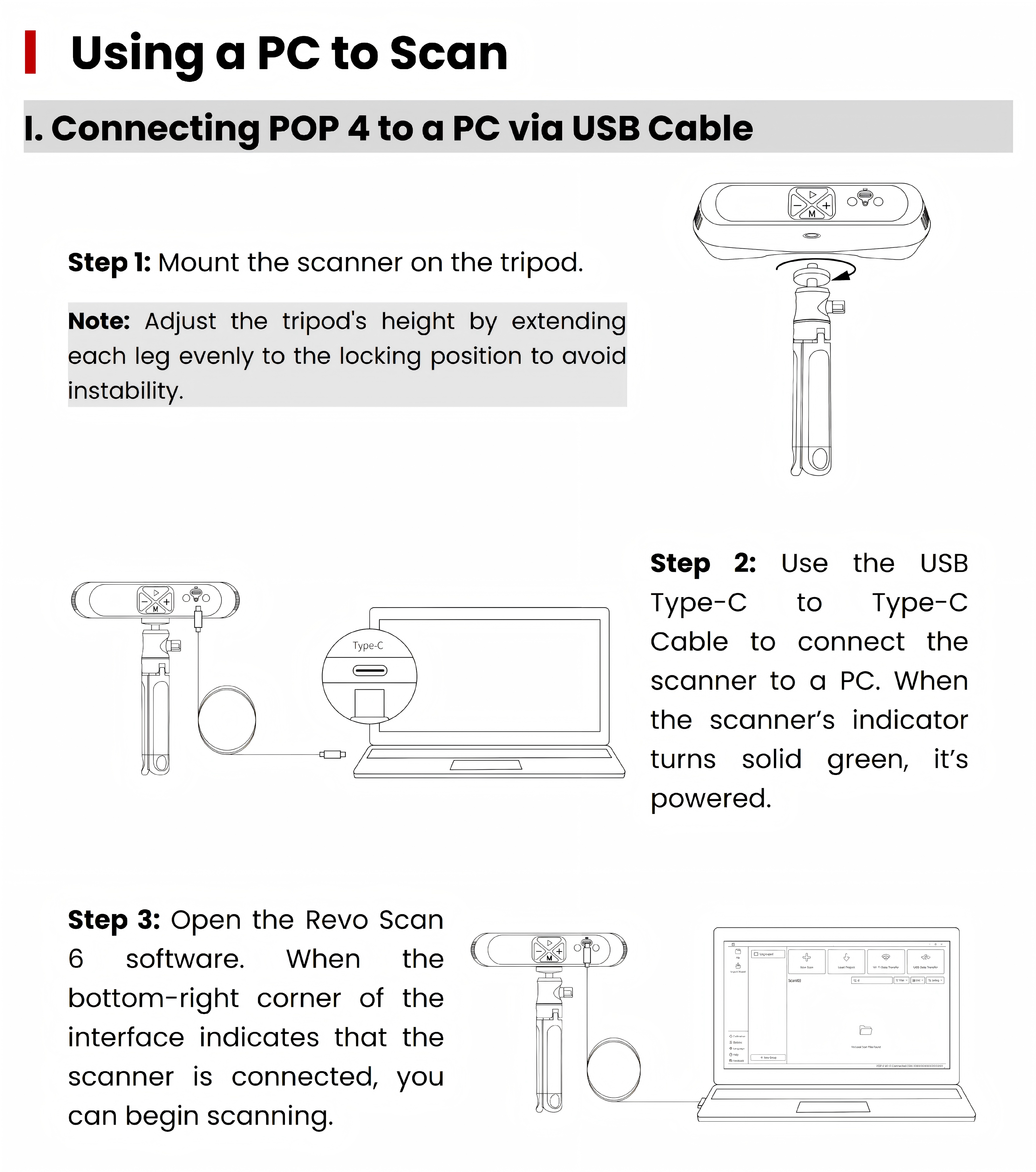
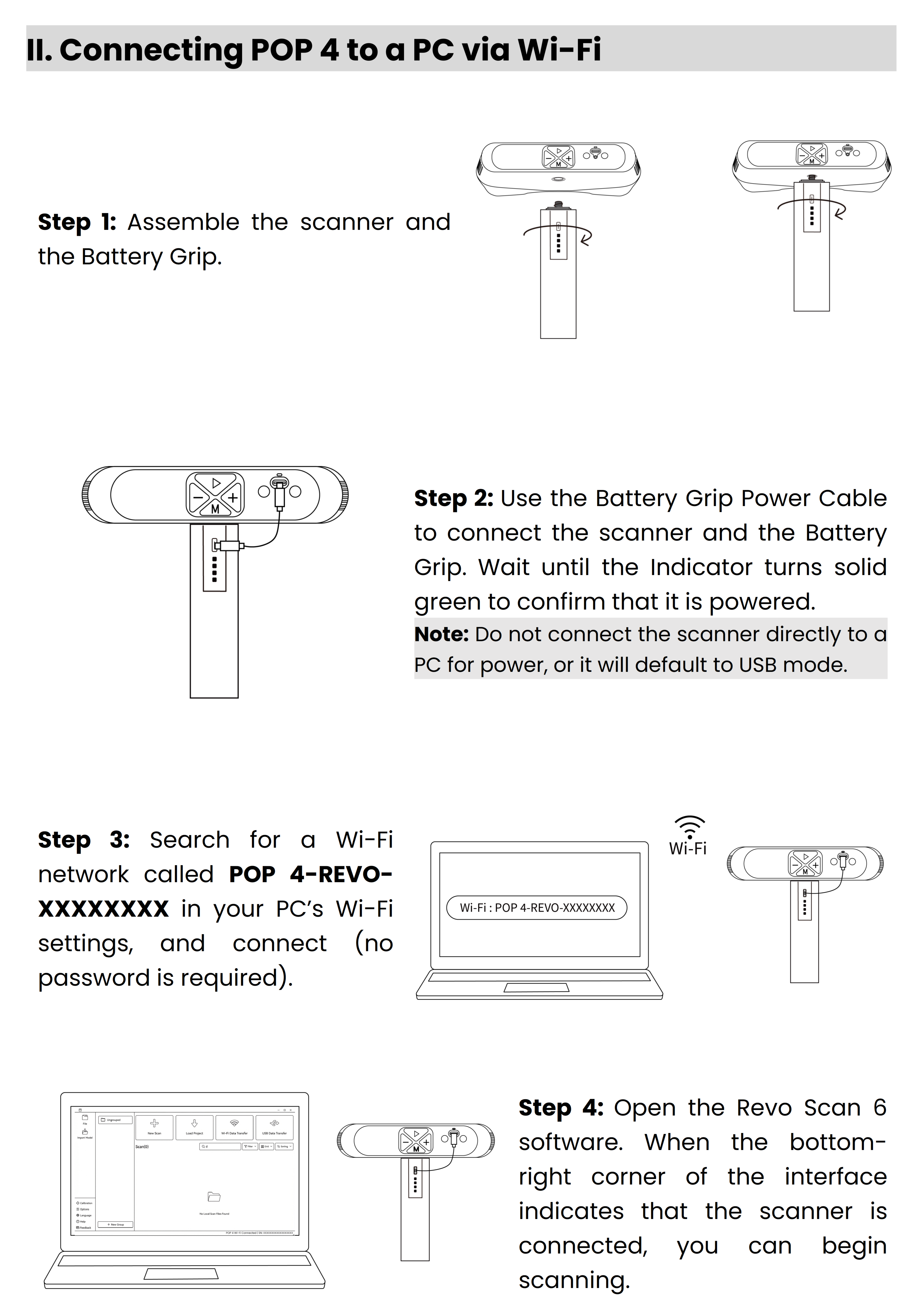
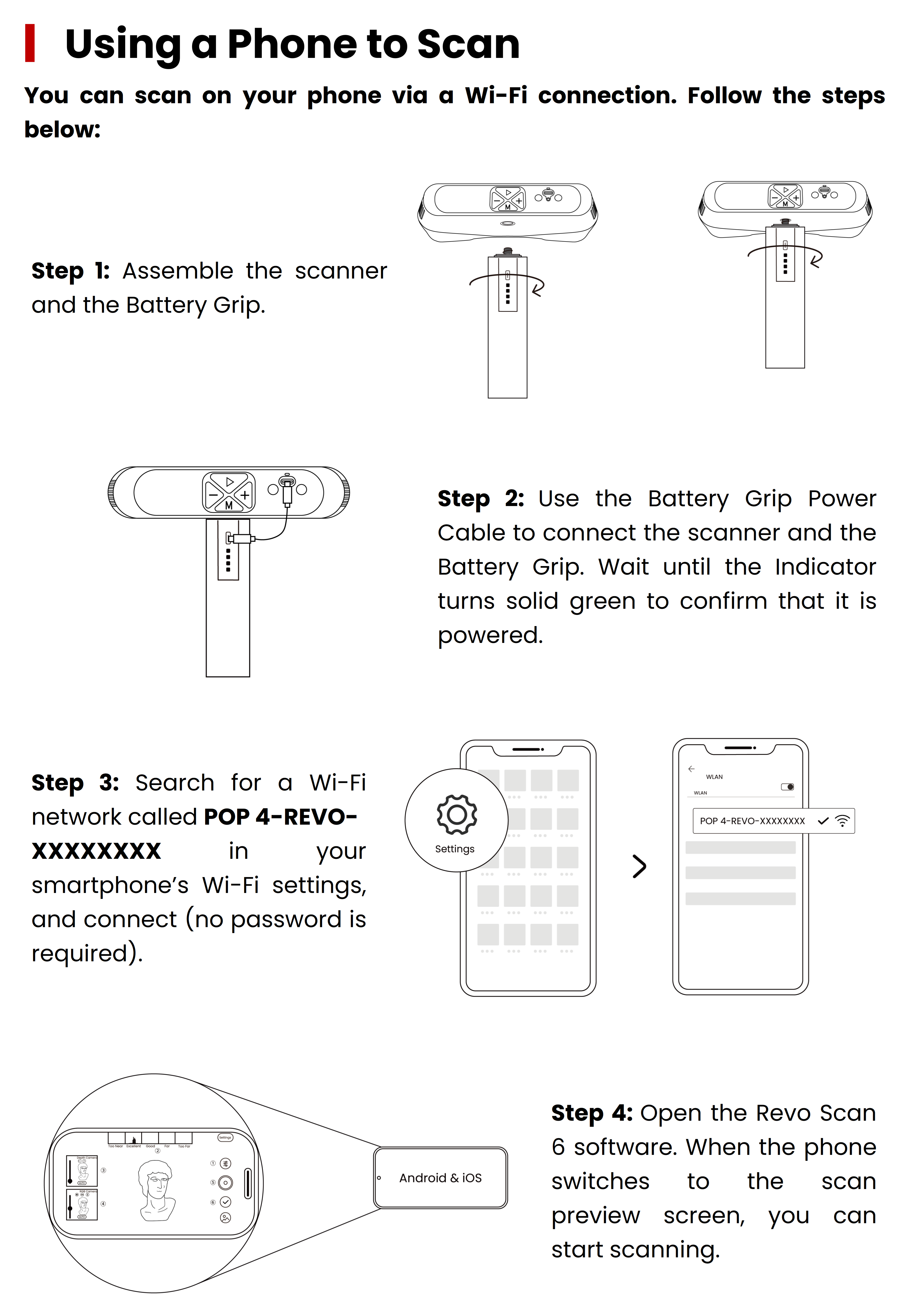
¶ 5. Scanner Calibration
Revo Scan 6 allows users to recalibrate the POP 4 to ensure optimal accuracy. You can first check the current accuracy using the software's calibration feature. If the results are suboptimal, follow the on-screen prompts to complete the calibration process.
¶ 5.1 Preparation Before Calibration
① Use a USB Type-C to Type-C cable to connect the scanner to the computer, then launch Revo Scan 6 on the Computer.
Note:Warm up the device for 10 minutes before calibration to ensure optimal accuracy.
② Place the Calibration Board, then click Calibration at the bottom-left of the home page to enter the calibration process.
③ Adjust the ambient lighting to avoid an environment that is too dark or too bright.
④ Scan the QR code on the back of the Calibration Board to import its metrology data.
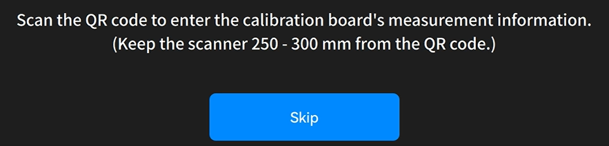
⑤ Place the calibration board. Follow the on-screen operation guide diagram to perform the calibration practice.
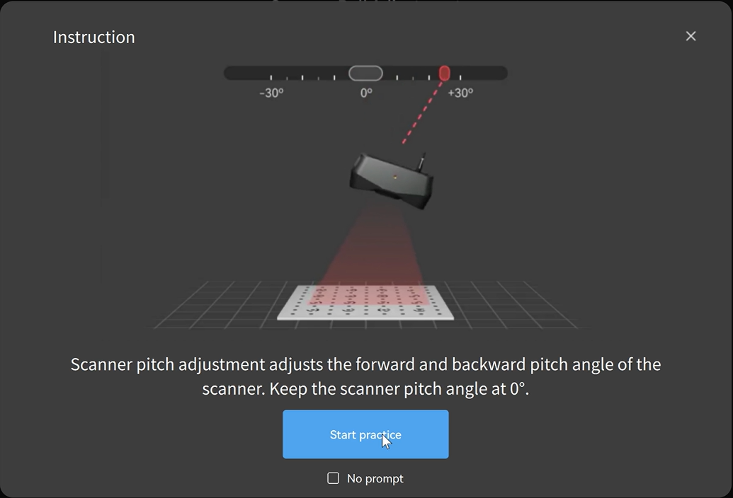
⑥ After completing the practice, click "Start Calibration" to enter the scanner Accuracy Check page and decide whether to continue calibration based on the accuracy results.
¶ 5.2 Calibration
① Following the reference image on the left and the corresponding sliders, adjust the camera tilt angle, pitch angle, and height.
② Follow the progress bar at the top and gradually complete data collection from five angles: horizontal, left, right, front, and back.
③ Once the calibration accuracy meets the requirements, please save the calibration results.
④ Click "Complete" to return to the start page. The camera will restart automatically, and calibration is complete.
¶ 6. Tracking Mode & Scan Mode
The POP 4 features 4 Tracking Modes and 4 Scan Modes. The Tracking Mode determines how each frame aligns, while the Scan Mode governs data acquisition. Select the optimal combination based on your object's features, required detail, and application scenario.
¶ Tracking Mode
| Tracking Mode | Applications | Typical Objects |
|---|---|---|
 |
Suitable for objects with distinct geometric features and rich surface contours. Alignment and stitching can be completed based on the object's own structural features. | Human bodies, heads, statues, action figures, dolls, shoes, plaster busts, decorative ornaments, etc. |
 |
Suitable for flat, symmetrical, or geometrically featureless objects, achieving alignment by recognizing physical marker points. | Cubes, cylinders, spheres, regular box-shaped objects, flat panels, pipes, tanks, smooth casings, etc. |
 |
Suitable for large, featureless objects. Global marker points are used to improve stitching stability during large-area scanning. | Automotive parts, large sculptures, furniture, large moulds, large enclosures, equipment housings, door panels, sheet metal parts, etc. |
 |
Suitable for objects with distinct color textures, patterns, printed information, or natural grains. It aligns data based on surface visuals rather than geometry, making it ideal for shapes with low geometric detail but rich color variation, patterns, or text. | Painted models, printed carpet, labelled packaging boxes, book covers, wood-grain objects, stone-textured objects, products with text markings, decorative artwork, etc. |
¶ Scan Mode
POP 4 supports 4 scanning modes. Details are as follows:
| Tracking Mode | Feature Tracking, Marker Tracking, Global Marker Tracking, Color Tracking |
| Applications | Suitable for markerless free tracking of objects with geometric features, or marker tracking for featureless objects, ideal for detailed point cloud modeling. |
| Outdoor Scanning | × |
| Mobile Scanning | √ |
| Tracking Mode | Feature Tracking, Color Tracking |
| Applications | Enables high-speed markerless scanning for smoother and faster data acquisition. |
| Outdoor Scanning | √ |
| Mobile Scanning | √ |
| Tracking Mode | Feature Tracking, Color Tracking |
| Applications | Combining speed and precision, it captures highly accurate point clouds in fast motion, perfect for rapid, high-quality surface modeling. |
| Outdoor Scanning | × |
| Mobile Scanning | √ |
| Tracking Mode | Marker Tracking, Global Marker Tracking |
| Applications | It flawlessly handles high-reflectivity metal surfaces and dark objects, which is ideal for scanning complex surfaces. |
| Outdoor Scanning | √ |
| Mobile Scanning | × |
¶ 📖 Mode Selection Guide
Distinct geometric features (e.g., statues, human bodies, action figures, shoes, plaster busts, decorative ornaments)
Standard rapid modeling (prioritizing accuracy/details)
1. Full-field HD
2. Hybrid HD
Scanning dark or large objects
Symmetrical or large flat objects (e.g., cubes, cylinders, spheres, flat plates, pipes, smooth enclosures)
Standard rapid modeling
Highly reflective metal, pure black objects, or structures with deep holes and slots
Large objects with low geometric detail (e.g., automotive parts, large sculptures, furniture, large crates, door panels, sheet metal parts)
Standard rapid modeling
Highly reflective metal, pure black objects, or structures with deep holes and slots
Distinct color textures, patterns, or graphics (e.g., painted models, printed objects, book covers, wood/stone grain items, labeled packaging, decorative artwork)
Standard rapid modeling (prioritizing accuracy/details)
1. Full-field HD Scan
2. Hybrid HD Scan
3. VCSEL Rapid Scan
Scanning dark or large objects
¶ 7. First Scan
¶ 7.1 Full-field HD Scan
This scan takes the sample bust as an example to introduce the operation process of the Full-field HD Scan.
¶ 7.1.1 Start Scan
¶ Create a New Scan
Click "New Scan" on the File page.
① For tracking Mode, you can select Feature. Select Full-field HD for scan mode.
② Name the scan file, then click "Confirm" to enter the scanning interface.
¶ Scan Settings & Scan Control
① The scan accuracy is set to "High Accuracy" by default, and the scanning object is selected as "Normal."
② Use the preview window on the left to make sure the object is inside the camera view.
③ Adjust the distance between the scanner and the object, ensuring the distance indicator bar shows green.
④ Adjust depth camera exposure so red and blue areas are minimized. Gray indicates the best setting.
⑤ Enable Color Scanning if color model is needed.
⑥ Once settings are ready, click "Scan."
⑦ You can pause anytime and check the scanning progress in the model display area. If the scan is incomplete, click "Scan" again to continue.
¶ 7.1.2 Finish Scan
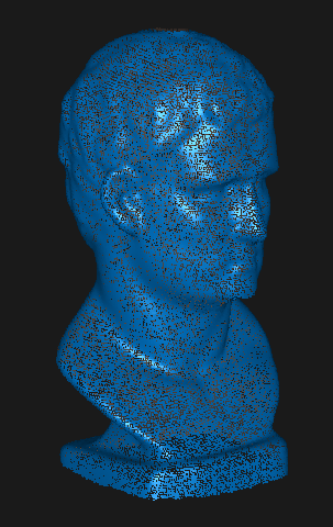
New users can use the following criteria to determine if scanning is complete:
• If the model preview displays fully.
• Ensure the real-time preview covers all surfaces of the target object, especially undersides, backsides, and crevices.
• Pause scanning to check for unfilled areas or structural omissions in point cloud or preview models. (Small holes can be manually filled during post-processing.)
Click "Finish" to complete the scan. If the model is incomplete, click the "Scan" button to continue scanning.
¶ 7.2 VCSEL Rapid Scan
This scan takes the large deer sculpture as an example to introduce the operation process of the VCSEL Rapid Scan.
¶ 7.2.1 Start Scan
¶ Create a New Scan
Click "New Scan" on the File page.
① For tracking Mode, you can select Feature. Select VCSEL Rapid for scan mode.
② Name the scan file, then click "Confirm" to enter the scanning interface.
¶ Scan Settings & Scan Control
① The scan accuracy is set to "High Accuracy" by default, and the scanning object is selected as "Normal."
② Use the preview window on the left to make sure the object is inside the camera view.
③ Adjust the distance between the scanner and the object, ensuring the distance indicator bar shows green.
④ Adjust depth camera exposure so red and blue areas are minimized. Gray indicates the best setting.
⑤ Enable Color Scanning if color model is needed.
⑥ Once settings are ready, click "Scan."
⑦ You can pause anytime and check the scanning progress in the model display area. If the scan is incomplete, click "Scan" again to continue.
¶ 7.2.2 Finish Scan
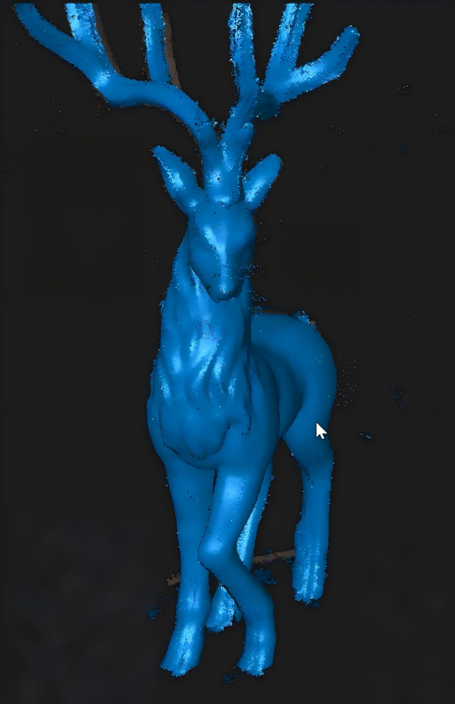
New users can use the following criteria to determine if scanning is complete:
• If the model preview displays fully.
• Ensure the real-time preview covers all surfaces of the target object, especially undersides, backsides, and crevices.
• Pause scanning to check for unfilled areas or structural omissions in point cloud or preview models. (Small holes can be manually filled during post-processing.)
Click "Finish" to complete the scan. If the model is incomplete, click the "Scan" button to continue scanning.
¶ 7.3 Hybrid HD Scan
This scan takes the colorful bird handicrafts as an example to introduce the operation process of the Hybrid HD Scan.
¶ 7.3.1 Start Scan
¶ Create a New Scan
Click "New Scan" on the File page.
① For tracking Mode, you can select Color. Select Hybrid HD Scan for scan mode.
② Name the scan file, then click "Confirm" to enter the scanning interface.
¶ Scan Settings & Scan Control
① The scan accuracy is set to "High Accuracy" by default, and the scanning object is selected as "Normal."
② Use the preview window on the left to make sure the object is inside the cam era view.
③ Adjust the distance between the scanner and the object, ensuring the distance indicator bar shows green.
④ Adjust depth camera exposure so red and blue areas are minimized. Gray indicates the best setting.
⑤ Enable Color Scanning if color model is needed.
⑥ Once settings are ready, click "Scan."
⑦ You can pause anytime and check the scanning progress in the model display area. If the scan is incomplete, click "Scan" again to continue.
¶ 7.3.2 Finish Scan
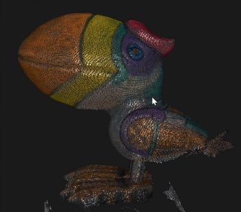
New users can use the following criteria to determine if scanning is complete:
• If the model preview displays fully.
• Ensure the real-time preview covers all surfaces of the target object, especially undersides, backsides, and crevices.
• Pause scanning to check for unfilled areas or structural omissions in point cloud or preview models. (Small holes can be manually filled during post-processing.)
Click "Finish" to complete the scan. If the model is incomplete, click the "Scan" button to continue scanning.
¶ 7.4 Laser Line Scan
¶ 7.4.1 Preparation Before Scanning
① Handle the Object
- Markers are required if you choose Laser Line scanning mode.
Don't use too many markers and ensure that at least 5 markers are placed irregularly per scanned frame.
For best accuracy, attach the markers to flat surfaces rather than curved ones. Also, please avoid using soft pads or cloths with markers.
You can also use the Marker Block Kit to create a more ideal and complete scanning environment.
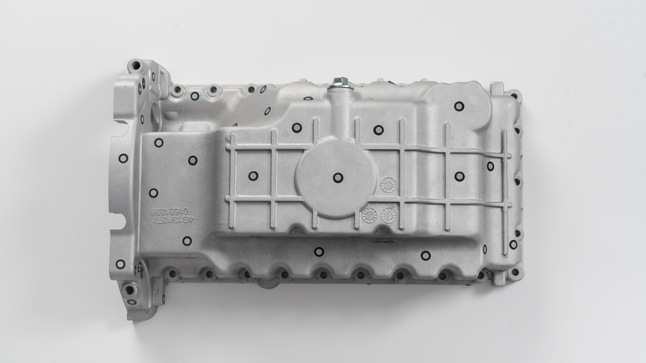
Marker Block Kit Quick Start Guide
- Using Scanning Spray
For transparent or specular objects (e.g., glass, stainless steel, electroplated surfaces), both line laser and structured light scanning require scanning spray.
For dark reflective or metallic reflective surfaces (e.g., black paint, machined aluminum alloy), line laser scanning can be performed without spray.
Note: Scanning spray can be purchased from Revopoint's online stores.
¶ 7.4.2 Start Scanning
¶ Create a New Scan
Click "New Scan" on the File page.
① Select"Marker" or "Global Marker". Select"Laser Line"in scan mode. For more details about mode selection, please refer to Tracking Mode & Scan Mode.
② Name the scan file, then click "Confirm" to enter the scanning interface.
¶ Scan Settings & Scan Control
① Enter the scan interface. Select laser type: Single Line/Cross Line.
② Set Accuracy and Object Type.
③ Set the target point distance. Larger spacing scans faster, while smaller spacing gives finer detail.
④ Adjust the distance between the scanner and the object, ensuring the distance indicator bar shows green.
⑤ Adjust the exposure of the depth camera to ensure that the laser line is clearly visible in the depth camera preview window.
⑥ Once settings are ready, click "Scan."
⑦ You can pause anytime and check the scanning progress in the model display area. If the scan is incomplete, click "Scan" again to continue.
¶ 7.4.3 Finish Scan
New users can use the following criteria to determine if scanning is complete:
• If the model preview displays fully.
• Ensure the real-time preview covers all surfaces of the target object, especially undersides, backsides, and crevices.
• Pause scanning to check for unfilled areas or structural omissions in point cloud or preview models. (Small holes can be manually filled during post-processing.)
-incomplete.png)
Click "Finish" to complete the scan. If the model is incomplete, click the "Scan" button to continue scanning.
¶ 7.5 Outdoor Scan
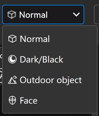
Both Line Laser and VCSEL Rapid modes support outdoor scan.
When scanning outdoors, select "Outdoor object" in Object Type.
- If you use Laser Line Scanning Mode for outdoor scanning under strong sunlight, it is recommended to purchase the Outdoor Blue Filters to improve the scanning results.
- Outdoor Blue Filters are not suitble for Full-Field HD/Hybrid HD/VCSEL Rapid Mode.
- For outdoor scanning, avoid rainy or windy weather to prevent water damage or reduced data accuracy from wet surfaces.
¶ 7.6 More Tips
Optimal results require proper parameter settings, which affect model integrity, clarity, and post-processing efficiency. Refer to Scanning Parameters Settings in Revo Scan 6's user manual for guidance on detailed settings.
¶ 8. Model Processing and Advanced Functions
¶ 8.1 One-click Edit
¶ 8.2 Manual Processing
This mode offers greater flexibility and is suitable for users who have higher requirements for model quality. Available functions include: Point Cloud, Mesh, Texture, Alignmentand Key Frames Edit, click the link to view the detailed introduction.
¶ 8.3 AI Object Segmentation and Tracking Function
Object Segmentation: Uses AI object recognition and tracking technology. After selecting the target object region, the software can continuously track that region during scanning, automatically remove irrelevant environmental point clouds, and output independent object point cloud data. For details, see:Revo Scan 6 Software User Manual - Object Segmentation
Remove Background: Uses AI background recognition and filtering technology. After selecting the background area to be removed, the software can continuously ignore that area during scanning and automatically retain the target object's point cloud. For details, see:Revo Scan 6 Software User Manual - Remove Background
¶ 8.4 3DGS Real Modeling Function
3DGS:Using scaled Gaussian splatter 3D modeling reconstruction, the point cloud and RGB scan data are converted into a realistic Gaussian model, enhancing realism while maintaining accuracy. This feature is available only after meshing has been completed.
¶ 8.5 Mirroring
POP 4 also supports wireless casting to a phone via Revo Mirror:
① Visit the Revopoint official website and go to “Support - Download” menu to download and install Revo Mirror for both desktop and mobile.
② Mount the Battery Grip onto the scanner. Connect the Battery Grip to the scanner with the Battery Grip Power Cable.
③ Ensure both the computer and phone are connected to the network named "POP 4-REVO-XXXXXXXX." Open Revo Scan 6, wait for the scanner to connect and enter the scanning page, then click the mirroring button.
④ Tap the detected device to be mirrored in the mobile Revo Mirror app.
⑤ Follow the prompt on the PC to enter the PIN code to complete the initial pairing. Then, click “Enter Screen Mirror Mode” to control the scanning process.
For more information about software and screen mirroring, please refer to Revo Mirror User Manual.