¶ 1. Welcome
Welcome to your Revopoint software user manual! This manual provides Revo Scan 6's operation guide and instructions. Please read the manual before your first use. If needed, you can click on any topic in the navigation bar to quickly jump to that section.
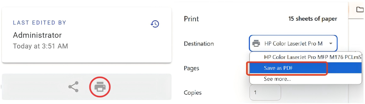
Manual Download:
If you need a PDF manual, click the Print Format button at the bottom of the navigation bar on the left side of the manual, and select "Save as PDF" from the options.
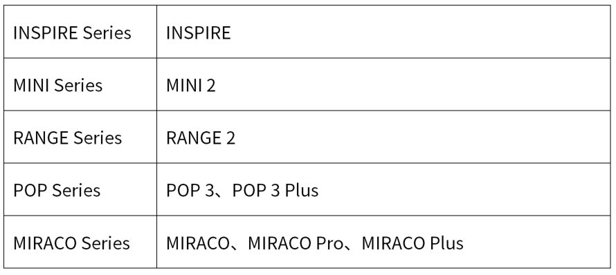
¶ Supported Scanner Models
¶ Before You Begin
- This manual applies to users on Windows and macOS (POP 4 Only). Mobile users can refer to the corresponding software user guide in Revo Scan 6 for iOS or Android.
- New users are encouraged to review the Glossary at the end of this document and familiarize themselves with any new terms before proceeding to get the most out of this guide.
- To ensure an optimal scanning experience, this software receives regular updates. We recommend visiting the Revopoint official website periodically to download the latest version.
- This manual is frequently updated to cover the product's latest features and improvements. While we strive to keep this manual updated, some discrepancies may occur. Your feedback and suggestions are welcome to help improve our manual.
¶ 2. Software Installation & Updates
¶ 2.1 Revo Scan 6 Upgrade Highlights (Compared with Revo Scan 5)
1) New File Management Page: Featuring file grouping to help you organize and manage your scans more efficiently.
2) Simplified File Structure: Revo Scan 6 replaces the complex project concepts of Revo Scan 5 with a simplified "one scan, one file" workflow, making file management clearer and easier to use.
3) Rebuilt Post-Processing Workflow:
① Advanced Fusion: Each file can now store up to five fusion and mesh results, preventing previous results from being overwritten and allowing multi-version data coexistence and iterative optimization.
② Simplified Post-processing Operations: A new quick-edit workflow lets you run preset actions with one click or customize parameters through a drop-down menu, significantly improving processing speed and usability.
4)Redesigned Visual Style: The main color scheme has been upgraded from black and red to black and blue, creating a more focused, modern, and professional visual experience.
5)View Layout Optimization: 3D view settings, display controls, and support tools are now placed directly in the main workspace, so key functions are easier to find and use.
¶ 2.2 System Requirements
| Supported Systems | Minimum | Recommended |
 |
RAM: ≥ 16 GB CPU: Intel i7 13th Gen or AMD Ryzen 7 5800 GPU (Optional): NVIDIA GeForceRTX 3060(8 GB) |
RAM: ≥ 32 GB CPU: Intel i9 12th Gen or better GPU (Optional): NVIDIA RTX 4060 (8 GB) or better |
 |
macOS (POP 4 Only) System Version: macOS 11.0 or better CPU: M1 Pro/Max/Ultra RAM: ≥ 16 GB |
macOS (POP 4 Only) System Version: macOS 11.0 or better CPU: M3 Pro/Max/Ultra or better RAM: ≥ 24 GB |
¶ 2.3 Software Download
Please visit the Revopoint official Support - Download page to download the Windows version of Revo Scan 6.
- Windows
Double-click the downloaded Revo Scan 6 software installation package and follow the installation wizard to complete the installation. Then, double-click the Revo Scan 6 icon to open the software.
- macOS
In Finder on your Mac, locate the download of Revo Scan 6, right-click it, go to Open With, and click Installer, then follow the installation wizard. Once finished, double-click the Revo Scan 6 icon to open it.
Note: You may need to enable your Mac to install non-App store software.
Go to the Apple menu > System Settings, click Privacy & Security in the sidebar, then go to Security on the right. (You may need to scroll down.) Change the security setting to "App Store and identified developers".
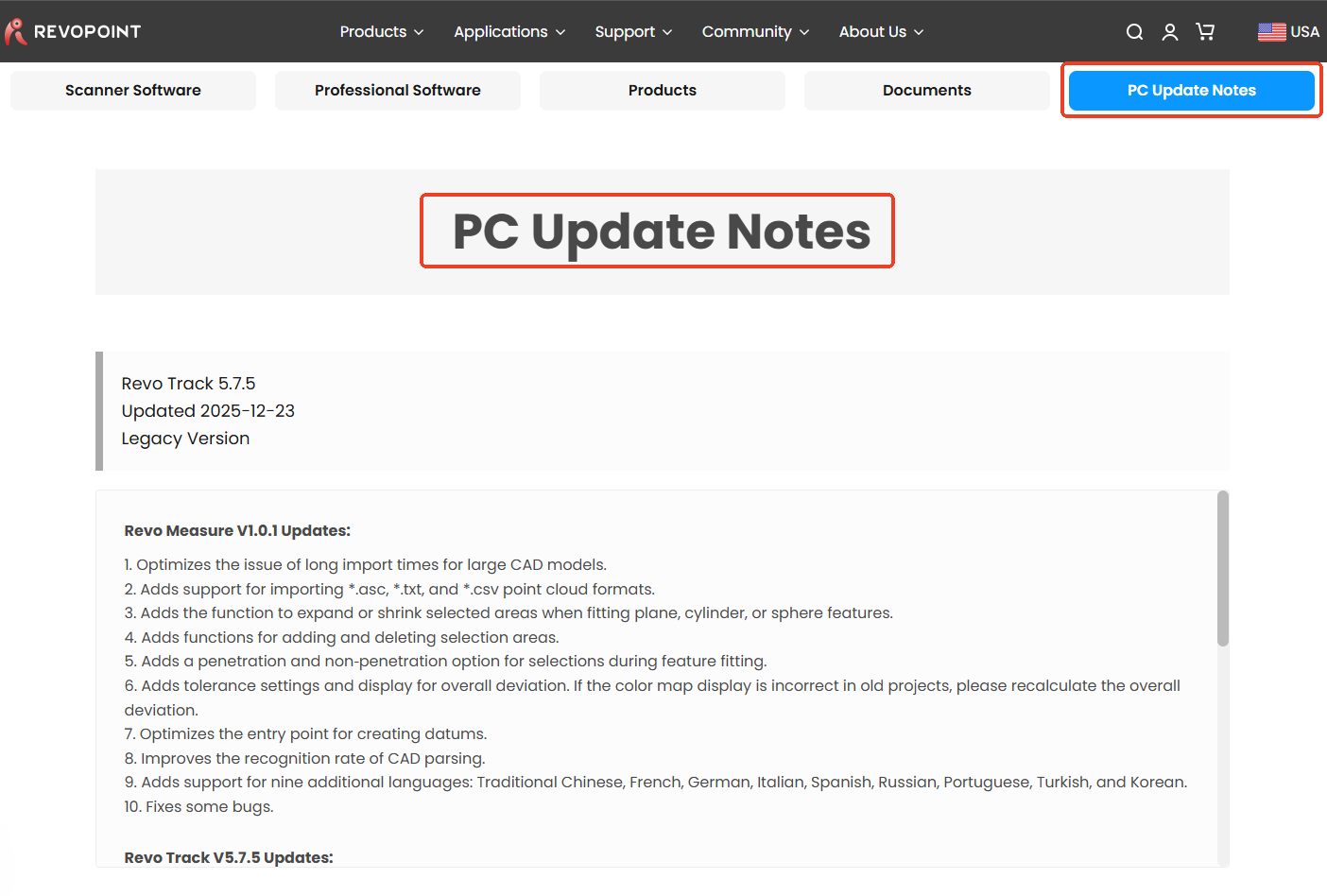
¶ 2.4 Software Update Notes
For subsequent updates and release notes, please click "PC Update Notes" on the Revopoint official website to view.
¶ 3. Scanner Connection
The scanner connection diagrams in this chapter are for reference only. Please refer to the actual connection operation.
¶ 3.1 USB Connection
MIRACO is an all-in-one scanner that can be used without external devices, so we generally recommend holding the product for scanning.
For advanced scanning settings or post-processing, MIRACO can be connected to Revo Scan 6 on your PC. The connection steps are as follows:
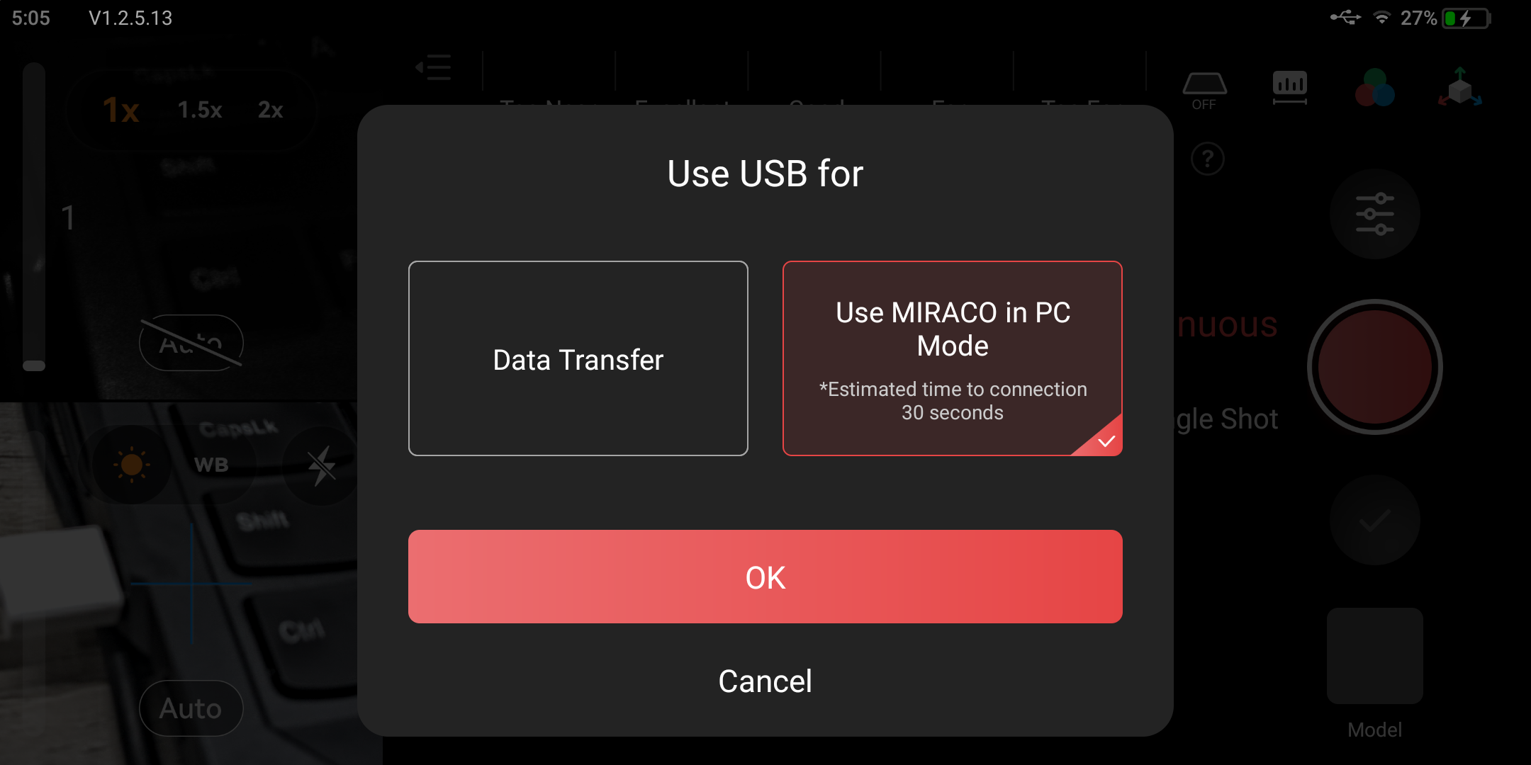
Step 1: Use the USB Type-C cable to connect to the computer, and open Revo Scan on the PC. A window will pop up for MIRACO - select "Use MIRACO in PC Mode".
Step 2: The "Scanner Connection Status" bar shows "Connected," indicating successful connection.
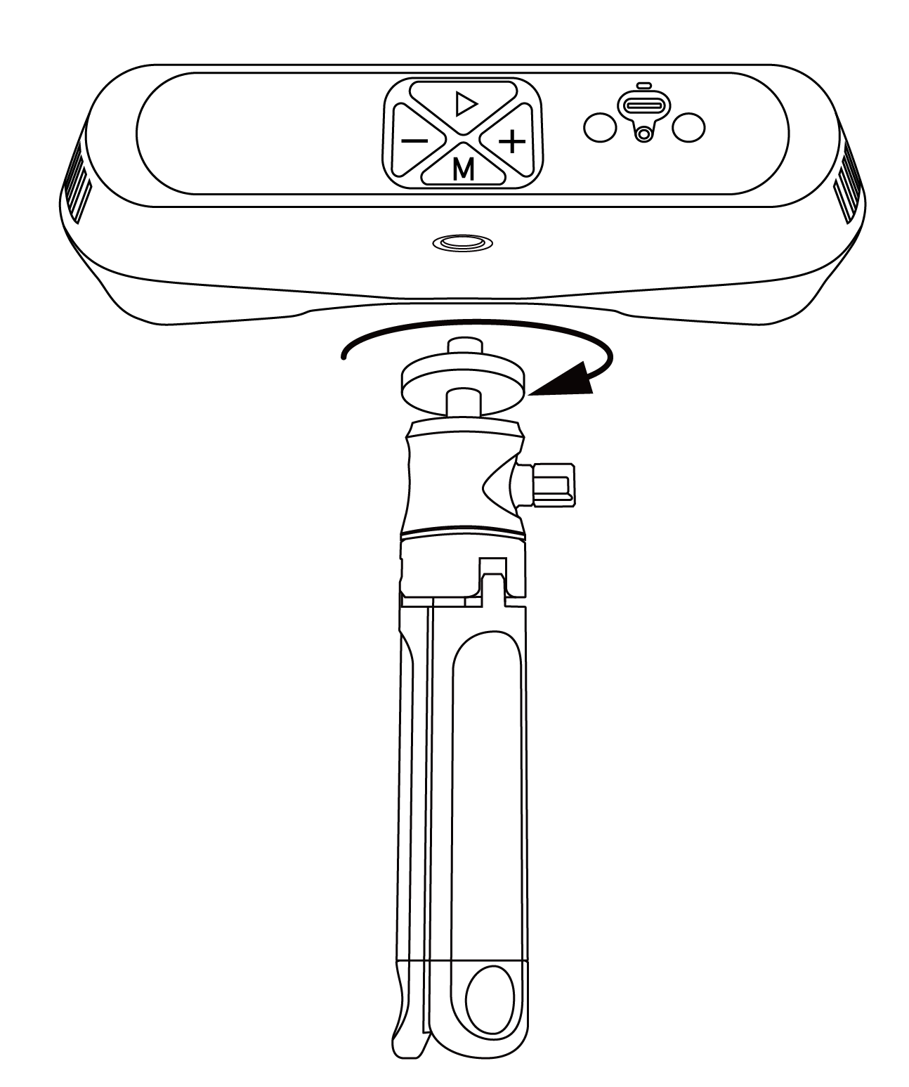
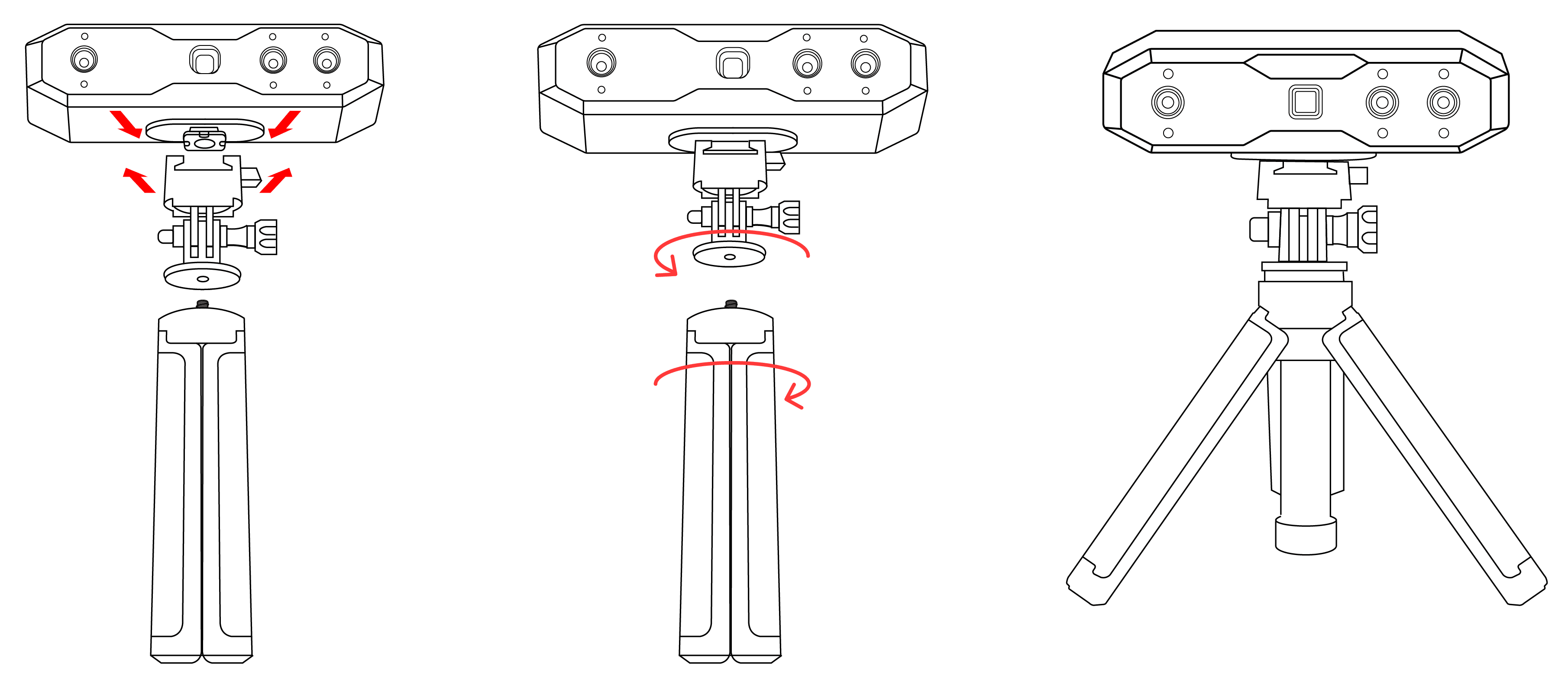
Step 1: Mount the scanner on the tripod.
Note: Adjust the tripod's height by extending each leg evenly to the locking position to avoid instability.
Step 2:Use the USB Type-C to Type-C Cable to connect the scanner to a PC. When the scanner’s indicator turns solid green, it’s powered.
Note: The POP 3 Plus must be used with the supplied USB Type-A to Type-C data cable. When connecting the scanner to a computer, use a USB 3.0 port or later.
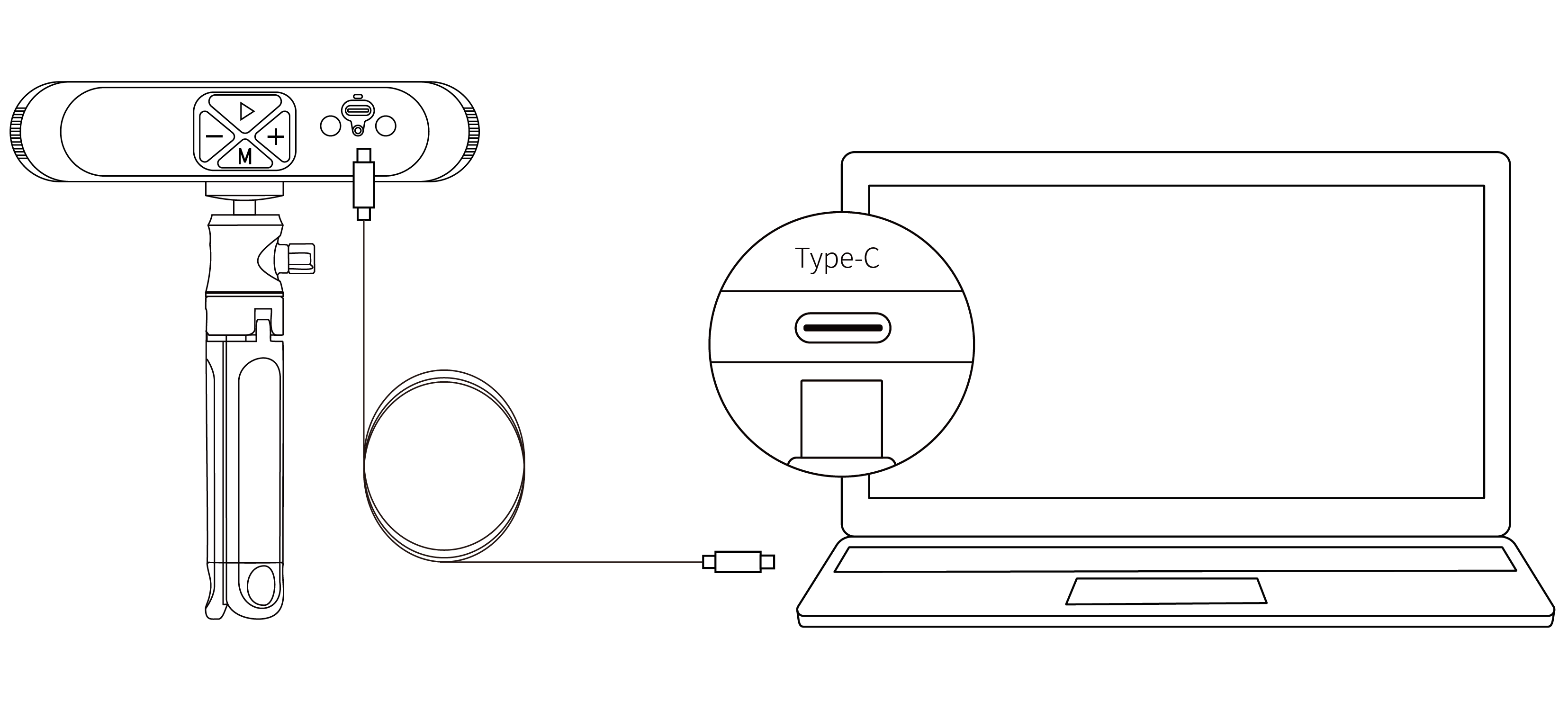
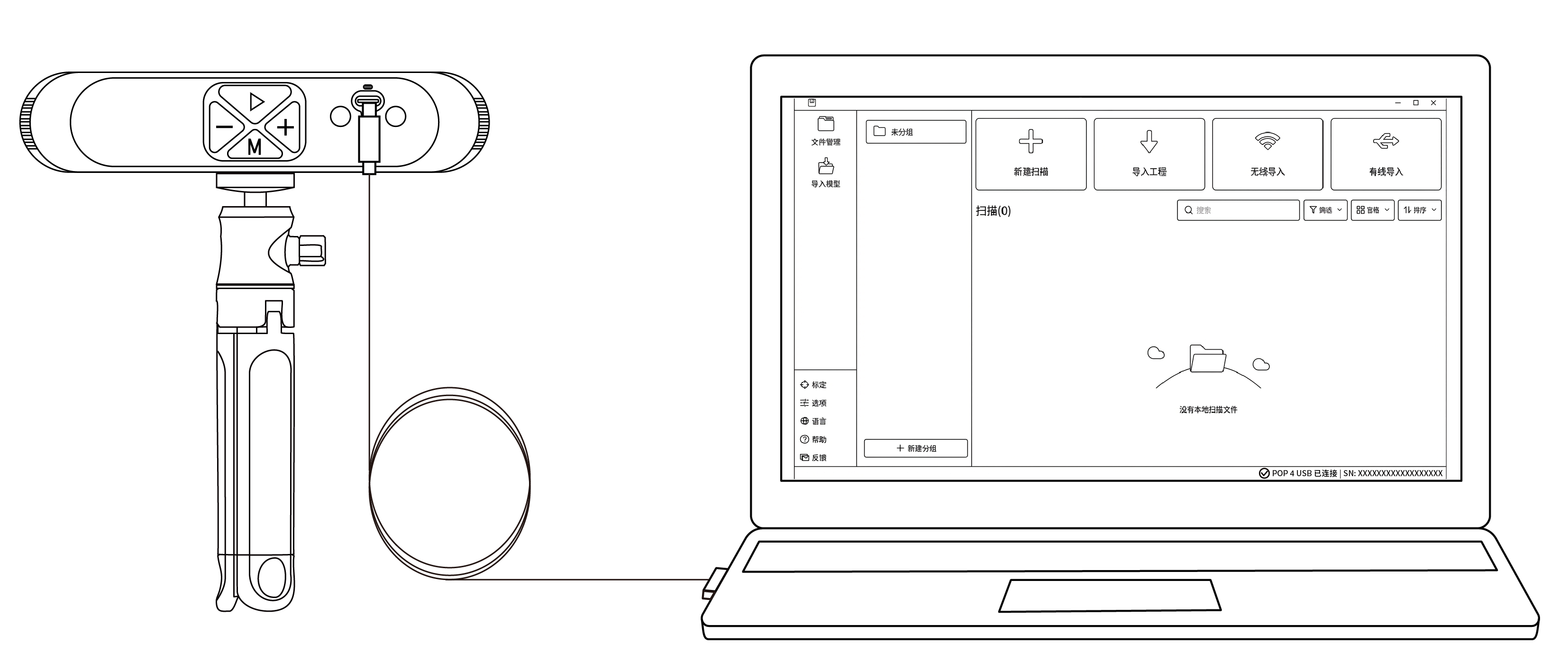
Step 3:Open the Revo Scan 6 software. When the bottom-right corner of the interface indicates that the scanner is connected, you can begin scanning.
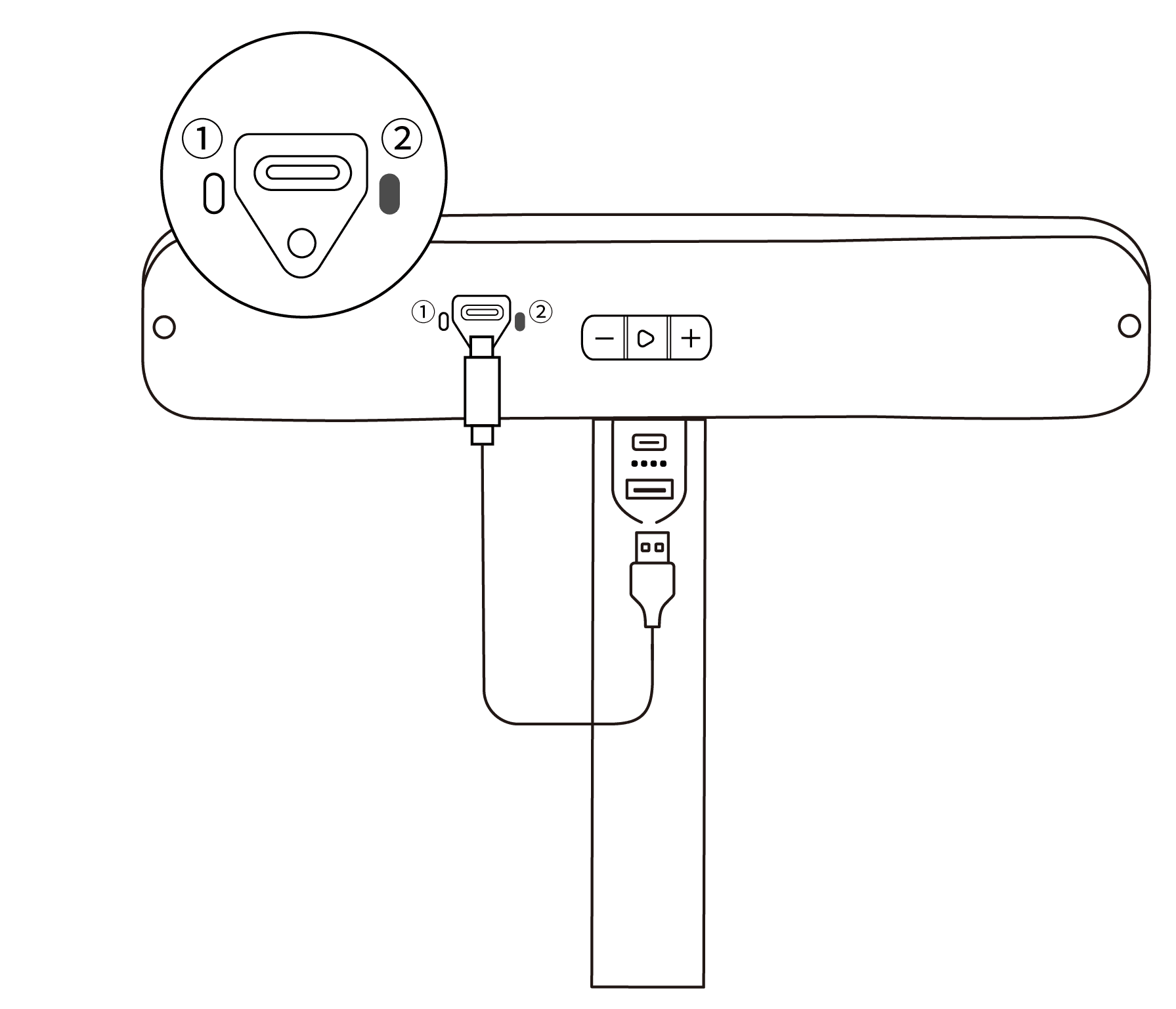
Step 1: Connect the Quick Mount Kit to the scanner,then screw the Tripod to the Quick Mount Kit.
Step 2: Use the USB Type-A to Type-C Cable to connect the scanner to a PC. When the scanner's indicator ② turns solid green, it's powered.
Note: If your computer does not have a USB Type-A port, use the USB Type-C to Type-A Adapter.
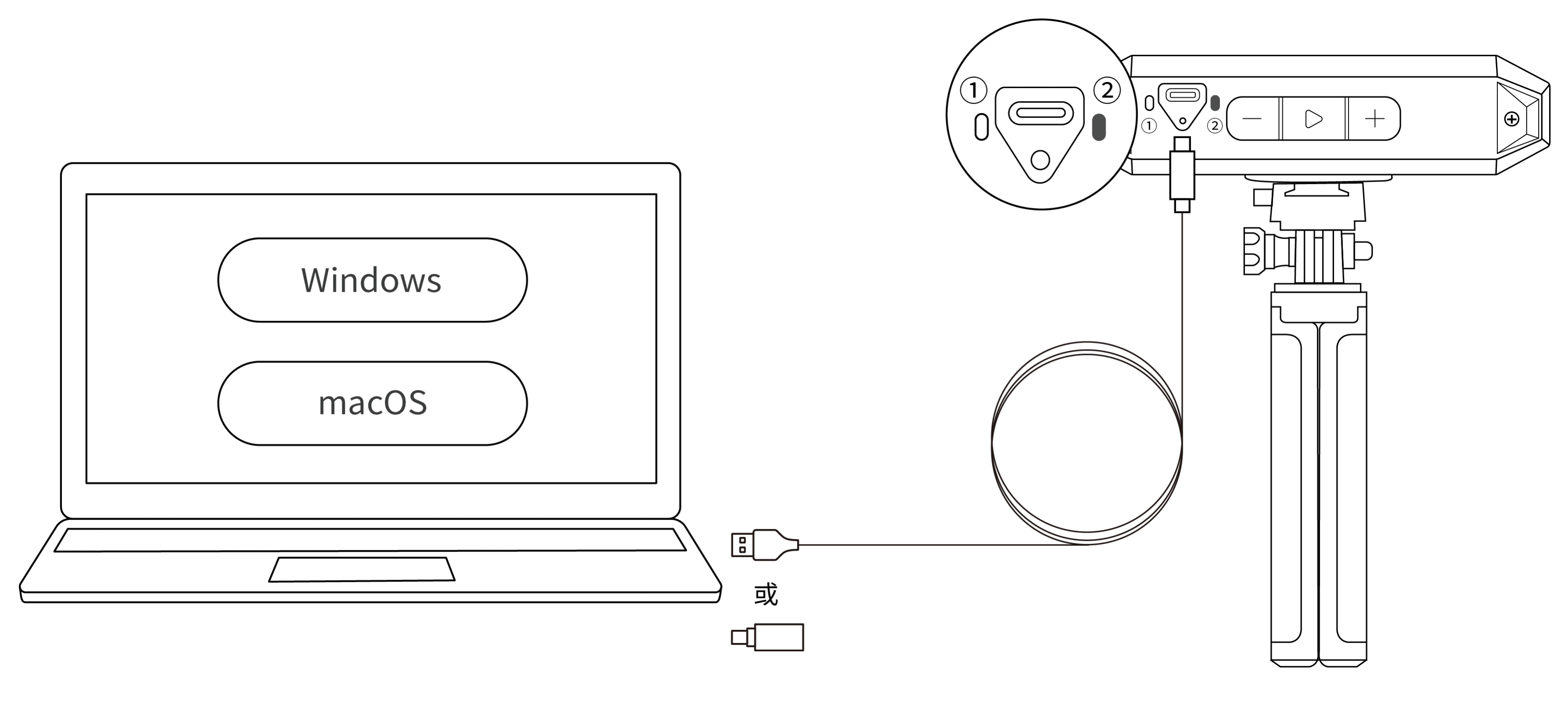
Step 3: Open Revo Scan 6, when the software shows Scanner Connected and the scanner's indicator ① turns solid blue, it's ready.
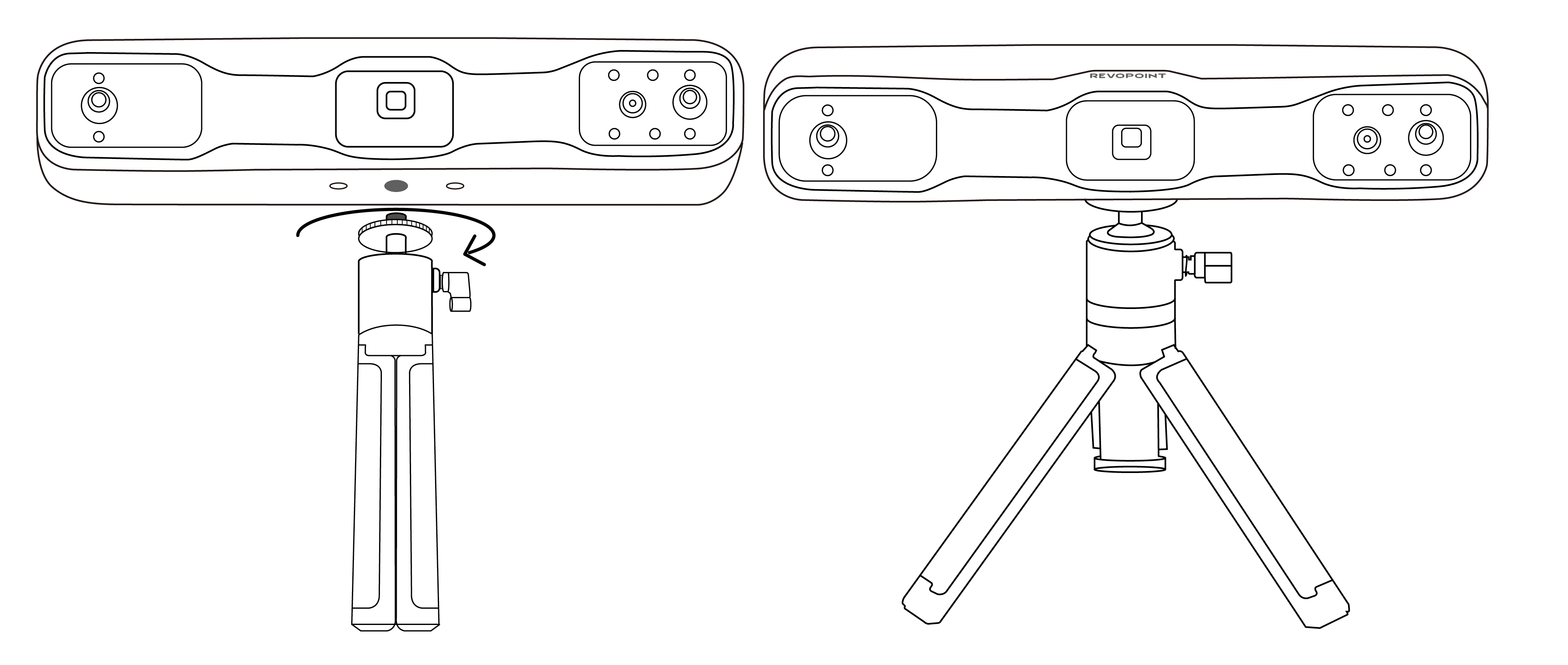
Step 1: Connect the Tripod to the scanner.
Step 2: Use the USB Type-A to Type-C Cable to connect the scanner to a PC. When the scanner's indicator ② tuns solid green, it's powered.
Note: If your computer does not have a USB Type-A port use the USB Type-C to Type-A Adapter.
Step 3: Open Revo Scan 6, when the software shows Scanner Connected and the scanner's indicator ① turns solid blue, it's ready.
¶ 3.2 Wi-Fi Connection
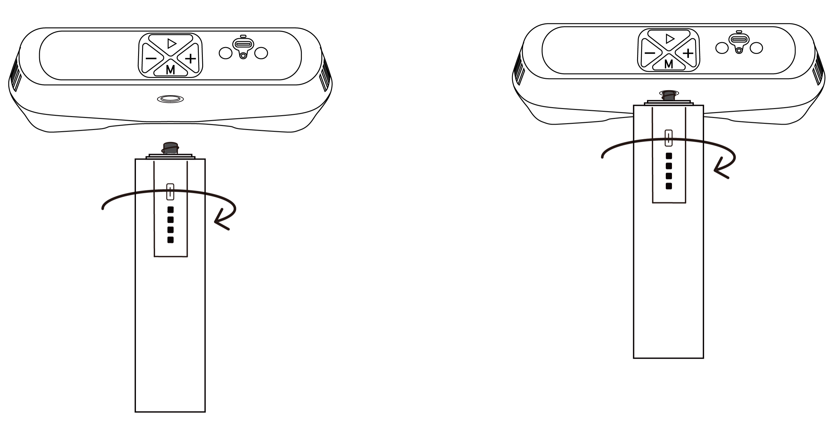
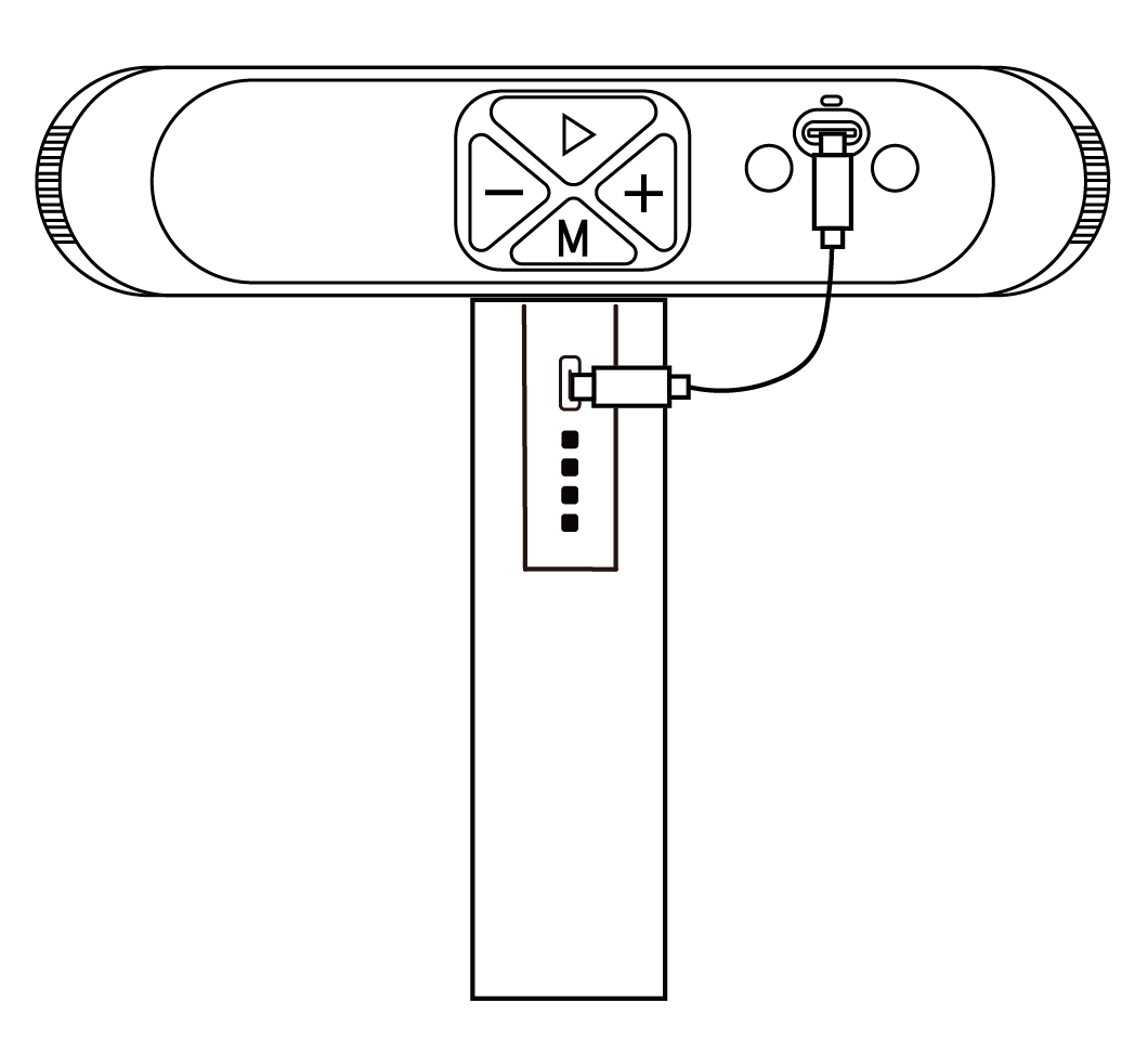
Step 1:Assemble the scanner and the Battery Grip.
Step 2:Use the Battery Grip Power Cable to connect the scanner and the Battery Grip. Wait until the Indicator turns solid green to confirm that it is powered.
Note:Do not connect the scanner directly to a PC for power, or it will default to USB mode.
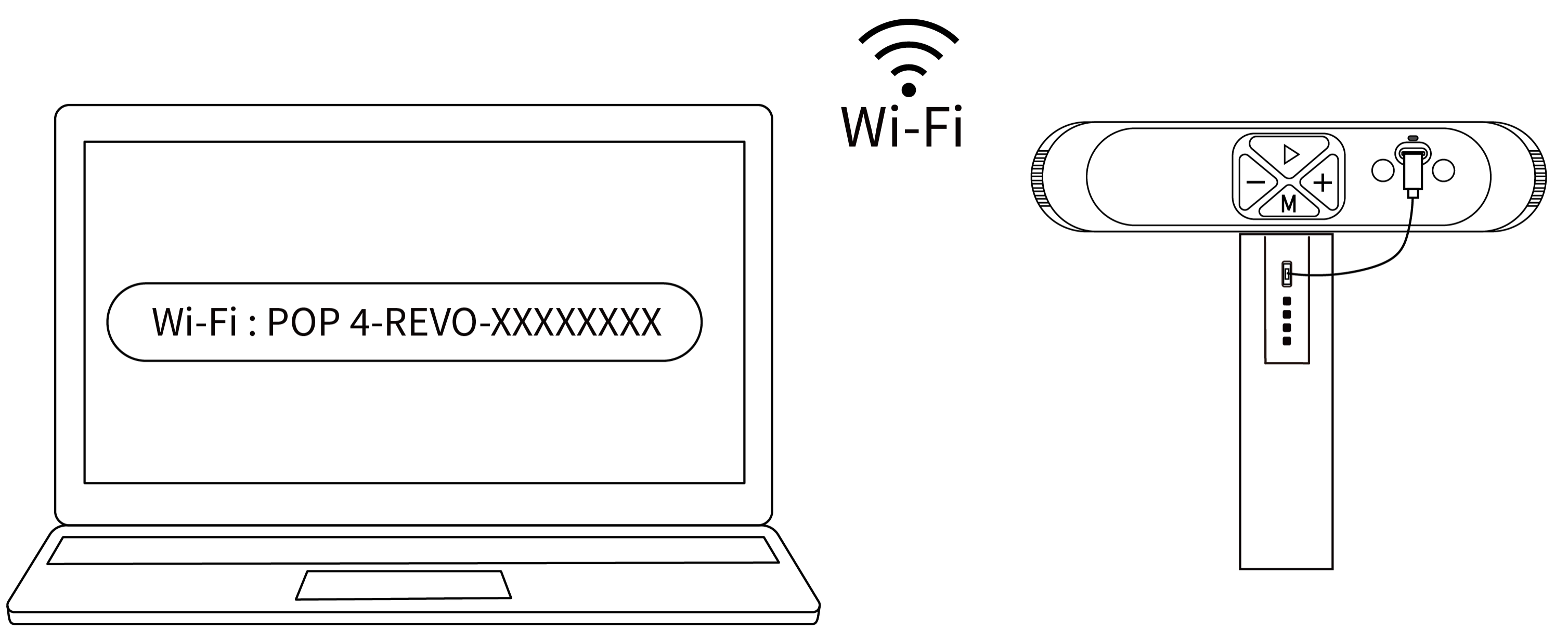
Step 3:Search for a Wi-Fi network called POP 4-REVO-XXXXXXXX in your PC’s Wi-Fi settings, and connect (no password is required).
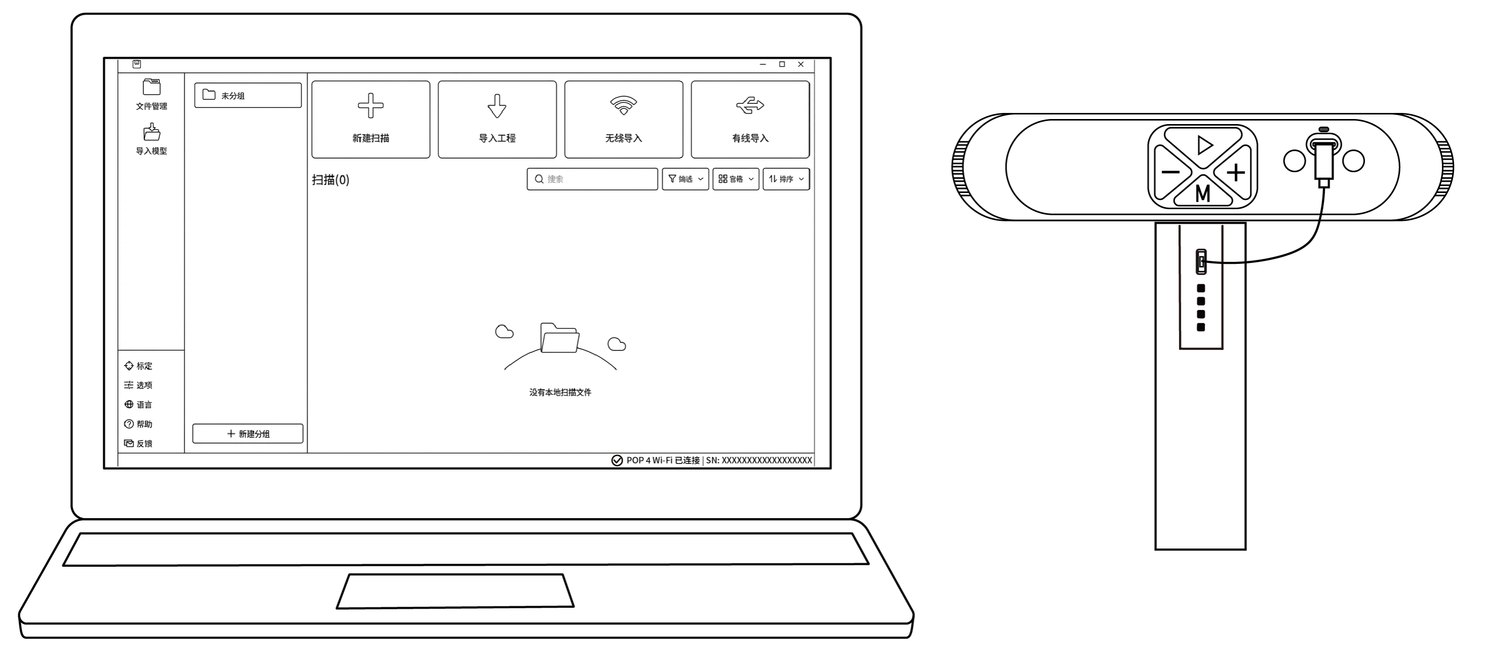
Step 4:Open the Revo Scan 6 software. When the bottom-right corner of the interface indicates that the scanner is connected, you can begin scanning.
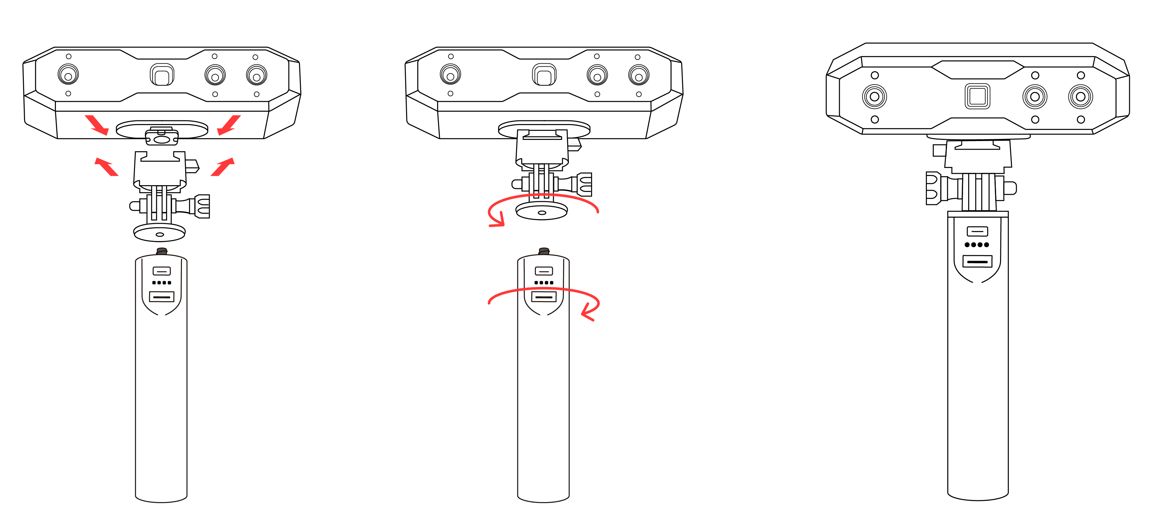
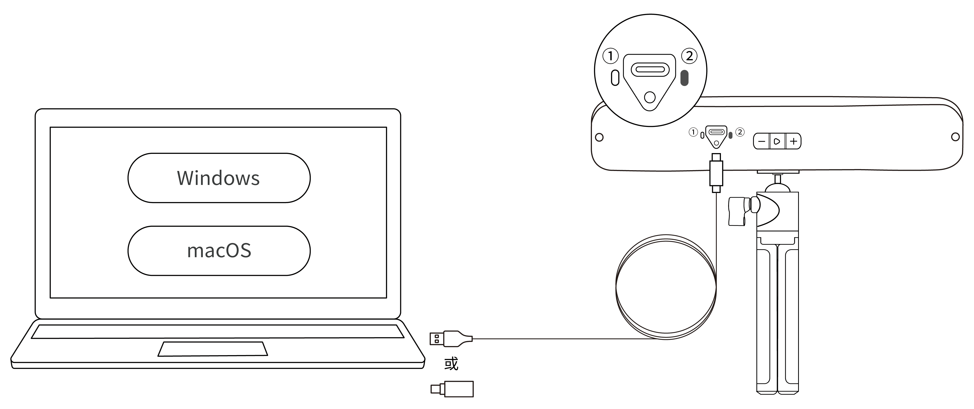
Step 1: Connect the Quick Mount Kit to the scanner, then screw the Power Bank Handle to the Quick Mount Kit.
Note: The Power Bank Handle can be purchased from the Revopoint online store.
Step 2: Use the USB Type-A to Type-C Cable to connect the scanner and Power Bank Handle. When the scanner's indicator ② turns solid green, it's powered.
Note: If your computer does not has a Type-A port, use the USB Type-C to Type-A Adapter.
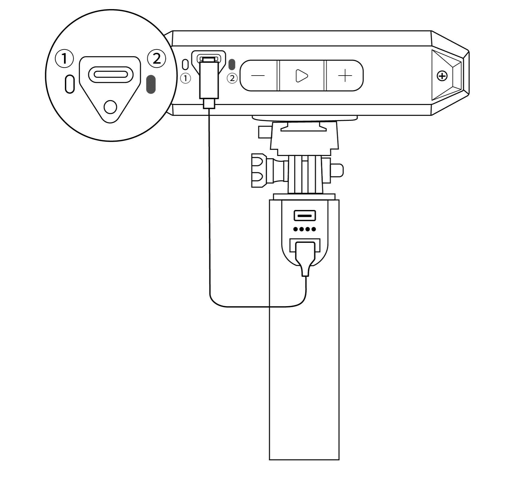
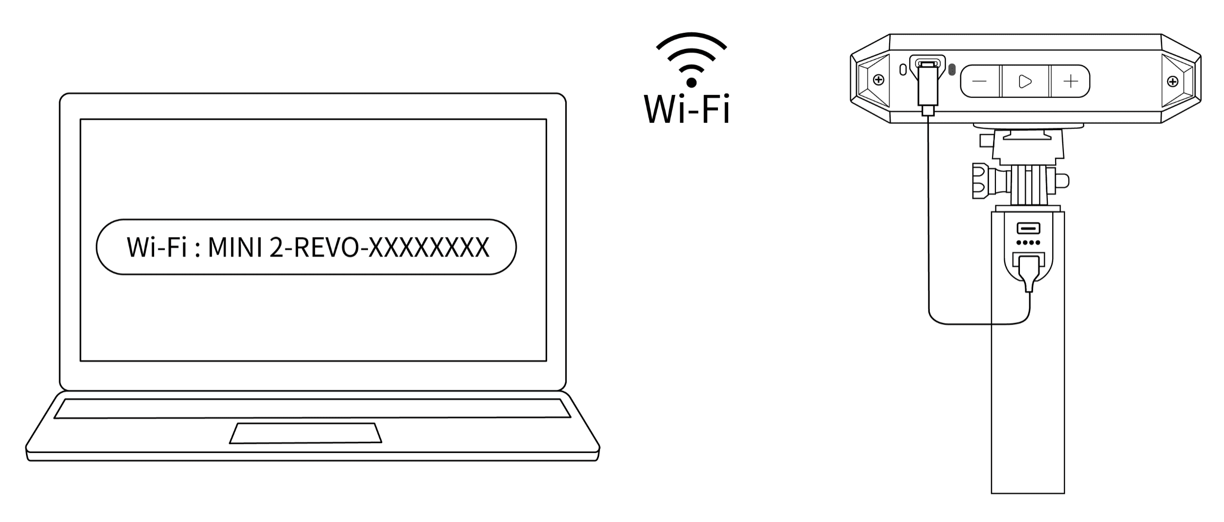
Step 3: In the computer's Wi-Fi list, locate and connect to the network named "MINI 2-REVO-XXXXXXXX" (no password required).
Step 4: Open the Revo Scan 6 software. Once the interface displays "Scanner Connected" and Indicator Light ① stays blue, you can start scanning.
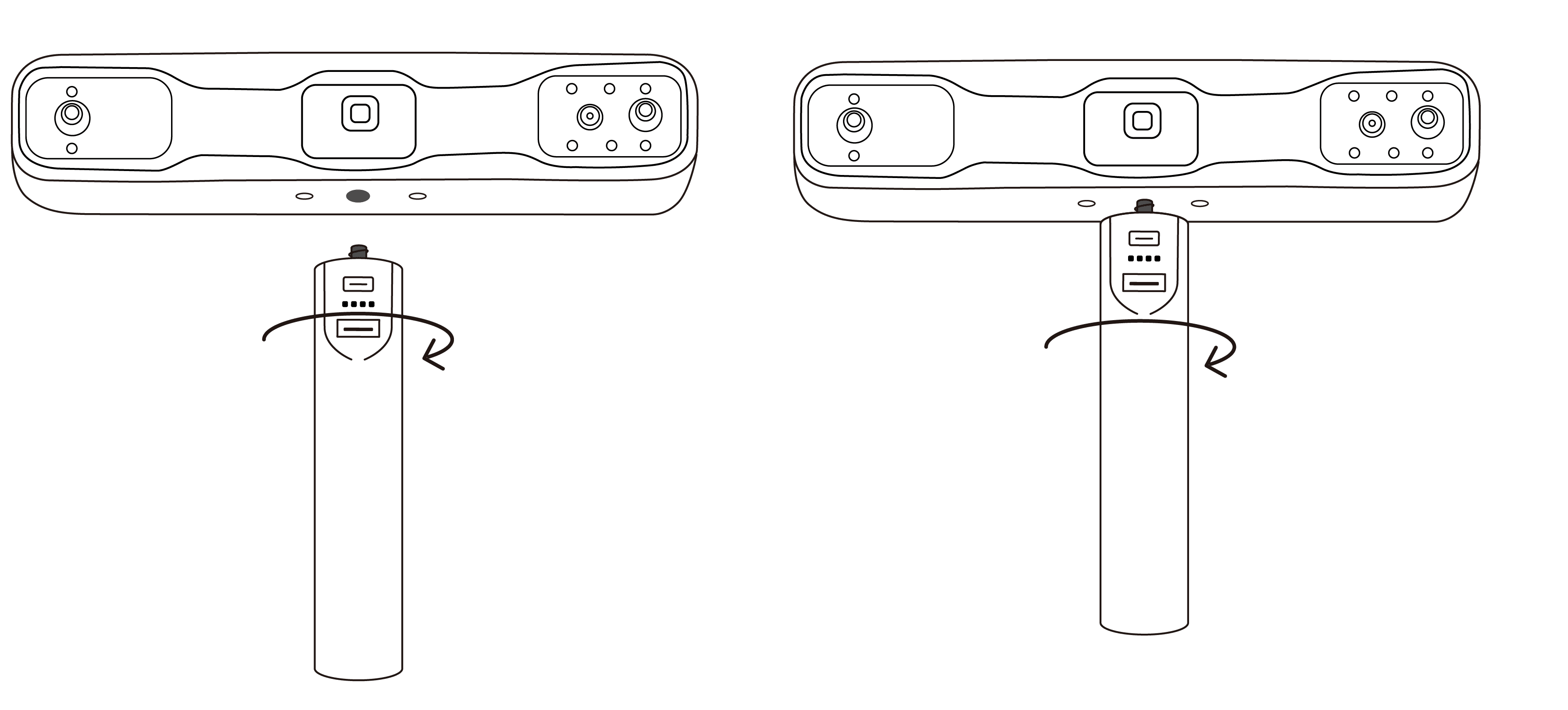
Step 1: Screw the scanner onto the Power Bank Handle.
Step 2: Use the USB Type-A to Type-C Cable to connect the scanner and Power Bank Handle. When the scanner's indicator ② turns solid green, it's powered on.
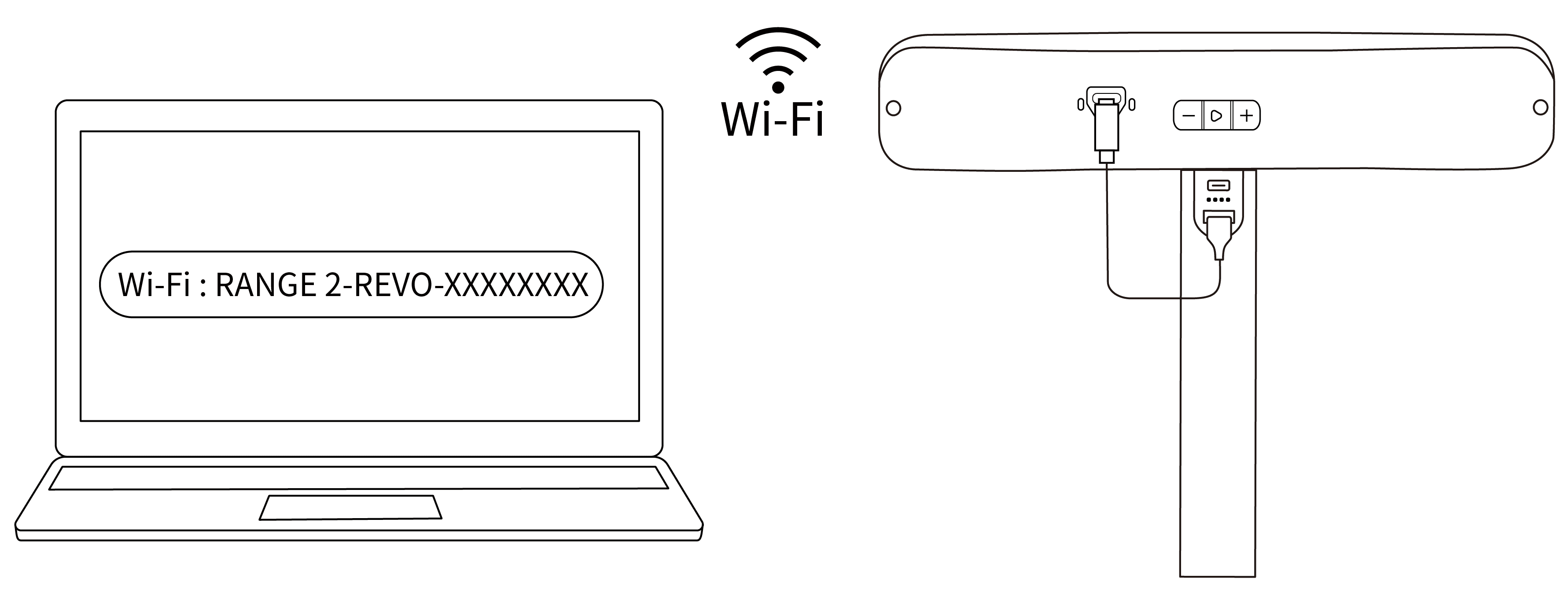
Step 3: Search for a Wi-Fi network called RANGE 2-REVO-XXXXXXXX in your PC's Wi-Fi settings, and connect (no password is required).
Step 4: Open Revo Scan 6, when the software shows Scanner Connected and the scanner's indicator ① turns solid blue, it's ready.
¶ 3.3 Connection Issues
POP 3 / POP 3 Plus / MINI 2 / RANGE 2
¶ 4. Scan Settings
¶ 4.1 Tracking Mode & Scan Mode
Other Compatible Products Connection Interface |
POP 4 Connection Interface |
¶ 4.1.1 Tracking Mode
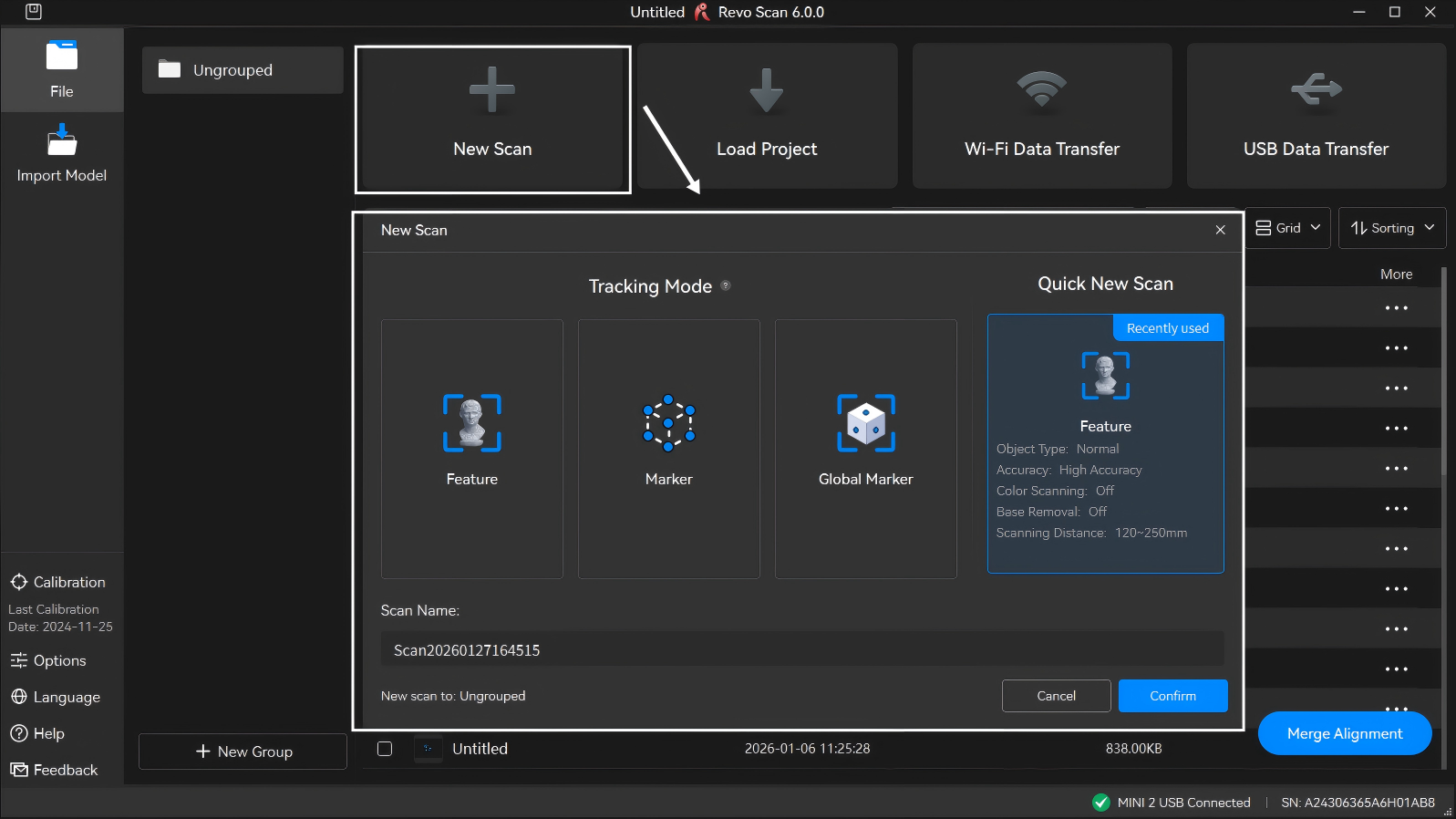
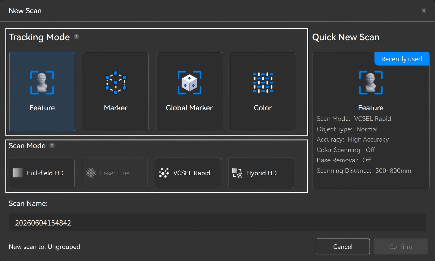
Click "New Scan" on File Management page and select corresponding tracking mode as needed.
• Feature Scan: Aligns data by identifying the geometric features on the object's surface. For objects with distinct surface features and no repeating patterns.
• Marker Scan: Aligns data by identifying the spatial location of the markers placed on or around the object's surface. For capturing large flat surfaces without distinct features. Marker points must be used to aid tracking.
• Global Marker Tracking: It is suitable for larger objects with indistinct geometric features. There are two steps: first, scan the markers to create global marker coordinates, and then scan the object based on these coordinates.
Global Marker Tracking Tutorial Video (For reference only)
• Color Tracking (POP 4 Only):Suitable for objects with distinct patterns, colors, or textures. Alignment and stitching rely on image texture features, ideal for objects with rich surface details.
Note: When using Color Tracking to scan smaller objects (≲12 cm × 6 cm), whether using turntable scanning or handheld scanning, it is recommended to place textured reference objects around the target and scan around it for at least 1.5 circles to improve tracking stability and accuracy.
¶ 4.1.2 Scan Mode (POP 4 Only)
• Full-Field HD Scanning: Projects fine structured light patterns. Suitable for markerless free tracking of objects with geometric features, or marker tracking for featureless objects, ideal for detailed point cloud modeling.
• VCSEL Rapid Scanning: Projects high-density dot patterns. Enables high-speed markerless scanning in feature-tracking mode for smoother and faster data acquisition.
Note: When scanning outdoor objects in this mode, do not install the outdoor blue filters, as it may affect scan quality.
• Hybrid HD Scanning: Powered by coordinated dual projectors, it captures highly accurate point clouds in fast motion, perfect for rapid, high-quality surface modeling.
• Laser Line Scanning:
① 30-Cross Blue Laser Lines Scanning: Projects 30 crossed blue laser lines. In marker-tracking mode, it flawlessly handles high-reflectivity metal surfaces and dark objects.
② Single-Line Deep Hole Scanning: Projects a single high-quality blue laser line. In marker-tracking mode, it precisely captures 3D data from localized deep holes, grooves, and other narrow areas.
¶ 4.2 Scanning Parameters Settings
¶ 4.2.1 Scanning Accuracy
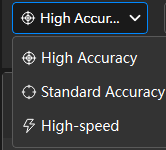
• High Accuracy: For capturing highly detailed objects. (Slower than scanning in standard accuracy mode.)
• Standard Accuracy: For capturing simple objects that don’t have complex and detailed surfaces.
• High-speed (18fps): For capturing larger objects or people/body parts quickly with faster frame rates and smooth frame stitching.
Note: Accuracy settings available, scanner speed, and size of the object capable of being captured are dependent on the scanner's model.
¶ 4.2.2 Object Type
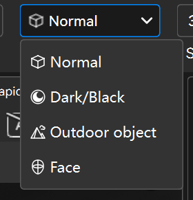
• Normal: This is the standard object type. Pick this type if the object doesn't match the other options below.
• Black Objects: Scan objects with dark surfaces, such as black or dark gray clothes. When using the Full-field or Auto Turntable scanning mode, some shiny dark items which will absorb or reflect light may still need to be treated with scanning spray to make them scannable.
• Outdoor Object (POP 4 Only): Scan objects in outdoor environments.
Note: For outdoor scanning, avoid rainy or windy weather to prevent water damage or reduced data accuracy from wet surfaces.
Lighting Environment Requirements: Multi-line Laser ≤ 50,000 lux,VCSEL ≤ 100,000 lux (When using the multi-line laser mode with an outdoor filter, scanning is possible in lighting conditions of up to 100,000 lux.)
• Faces: Designed for scanning human faces. (If using a MINI-series scanner, avoid staring directly at the projector for extended periods at close range.)
• Body: Scan people.
• Large: Scan larger objects quickly. Only available for certain scanners in high-speed accuracy mode.
Note: Different scanner models support varying object types and sizes.
¶ 4.2.3 Target Point Distance
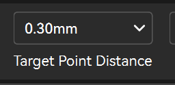
When using Laser Lines scanning modes, you can preset the target point distance, which is the space between adjacent point clouds during scanning. Setting a higher value will reduce scanning time but results in lower accuracy.
Note: It is recommended to use the default target point distance value. The value setting will remain unchanged when switching between the laser line modes.
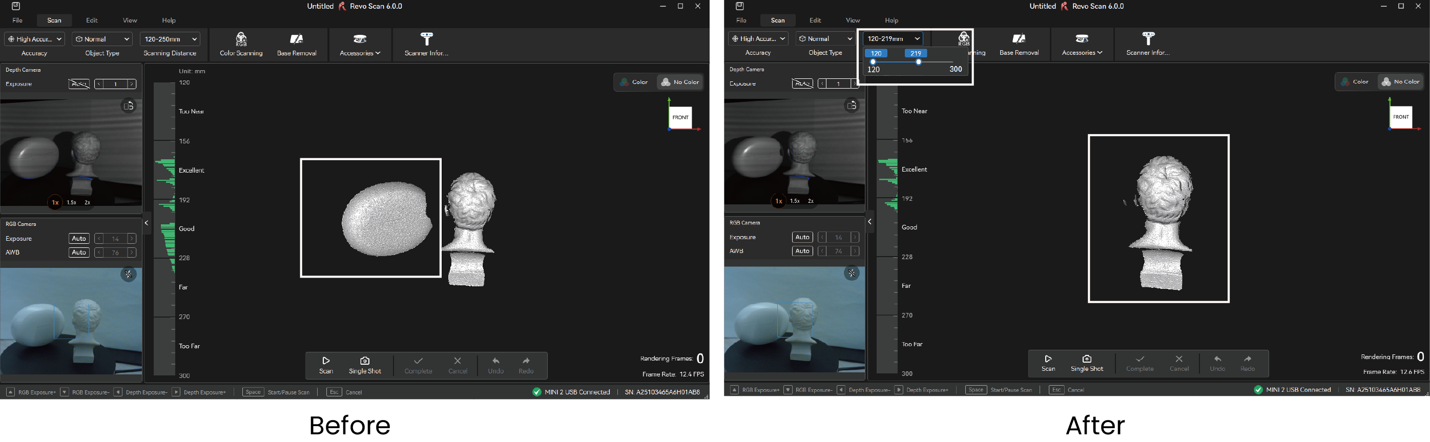
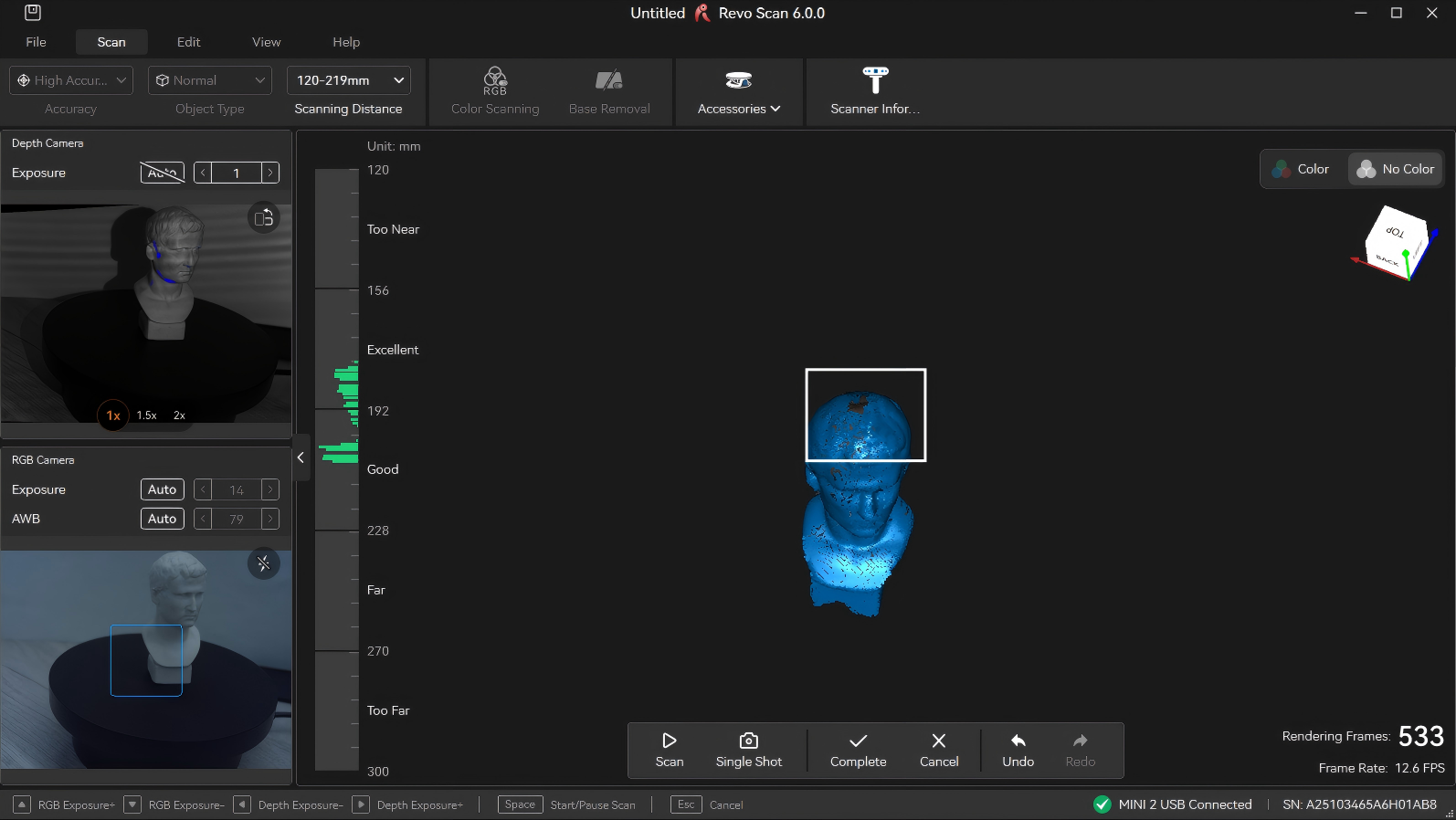
¶ 4.2.4 Scanning Distance
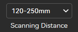
Use the slider to adjust the Depth Cameras'working distance to filter out unwanted background or foreground objects. Both a minimum and maximum distance can be set.
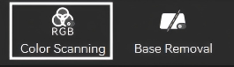
¶ 4.2.5 Color Scanning
Enable it to capture color data using the scanner's RGB camera. When performing a color scan, ensure the object is evenly lit with soft light for optimal color capture results.
Note: Texture mapping can be applied only when Color Scanning is enabled.
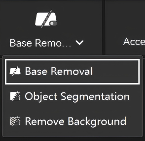
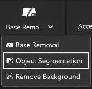
¶ 4.3 Base Removal
Toggle it on to enable automatic deletion of any unwanted flat surfaces detected (e.g., a table or floor). If scanning an object with many flat surfaces, turn this off to avoid deleting any of the object's surfaces.
¶ 4.4 Object Segmentation
Allows manual object selection for scanning (Left click to add, right click to remove/Long press to brush); it auto-tracks and scans continuously, with options to add or remove selections anytime. Recommended for complex backgrounds or uniform-colored objects.
Note: The object segmentation feature has certain computer performance requirements and supports macOS/Windows. The following GPU models have passed compatibility testing:
RTX 2060 Super、RTX 3070、RTX 4070、RTX 5070Ti、RTX 5090、RTX 2070 Super、RTX 3070 Ti、RTX 4070 Ti、RTX 5080、RTX A3000、RTX 2080 Super、RTX 3500 ADA、RTX 3080、RTX 3080 Ti、RTX 4080、RTX 4090、RTX A4500、RTX A5000、RTX 3050、RTX 3090、RTX 5060、RTX A6000、RTX 3060、RTX 3060 Ti、RTX 4060、RTX 4060 Ti、RTX 5060 Ti、RTX 5070
¶ 4.5 Remove Background
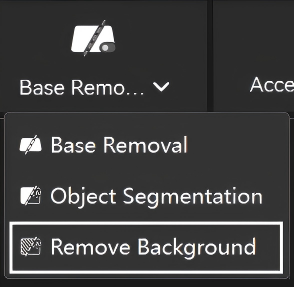
Allows manual selection (Left click to add, right click to remove/Long press to brush) of background regions to ignore while scanning the target object. You can add exclusions anytime. Recommended for simple backgrounds and colorful subjects.
Note: The remove background feature has certain computer performance requirements and supports macOS/Windows. The following GPU models have passed compatibility testing:
RTX 2060 Super、RTX 3070、RTX 4070、RTX 5070Ti、RTX 5090、RTX 2070 Super、RTX 3070 Ti、RTX 4070 Ti、RTX 5080、RTX A3000、RTX 2080 Super、RTX 3500 ADA、RTX 3080、RTX 3080 Ti、RTX 4080、RTX 4090、RTX A4500、RTX A5000、RTX 3050、RTX 3090、RTX 5060、RTX A6000、RTX 3060、RTX 3060 Ti、RTX 4060、RTX 4060 Ti、RTX 5060 Ti、RTX 5070
¶ 4.6 Accessory Connection
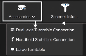
¶ 4.6.1 Dual-axis Turntable
Select the Dual-axis Turntable and connect it to the Revo Scan 6 via Bluetooth. Set parameters such as rotation speed, interval angle, and rotation direction according to your requirements.
- Rotation Speed (35–90 seconds per revolution): The time required for the turntable to complete a full rotation around the horizontal axis continuously. For example, 35 seconds per revolution means it takes 35 seconds to rotate one full circle.
- Tilt Angle (±30°): The angle of inclination of the Dual-axis Turntable's platform.
- Interval Angle (Adjustable in Auto Turntable mode): The rotational interval angle between adjacent photo positions. For instance, setting an interval angle of 30°will pause the turntable every 30° to capture a photo before continuing.
For more information about the Dual-axis Turntable, view Dual-axis Turntable Quick Start Guide or Dual-axis Turntable Usage Tutorial.
¶ 4.6.2 Handheld Stabilizer
Connecting the handheld stabilizer to the scanner and software can assist in stabilizing the scan, effectively improving issues such as low point cloud accuracy and loss of tracking caused by hand shake.
For more information about the Handheld Stabilizer, view Handheld Stabilizer User Manual.
¶ 4.6.3 Electric Large Turntable
The Revopoint Large Turntable is specifically designed for scanning large objects and human bodies. Powered by a power adapter, it has a maximum load capacity of 200 kg. Once connected, you can control the turntable's speed and direction via a remote controller or the Revo Assistant app.
For more information about the Large Turntable, view Large Turntable User Manual.
¶ 4.7 Scanner Information
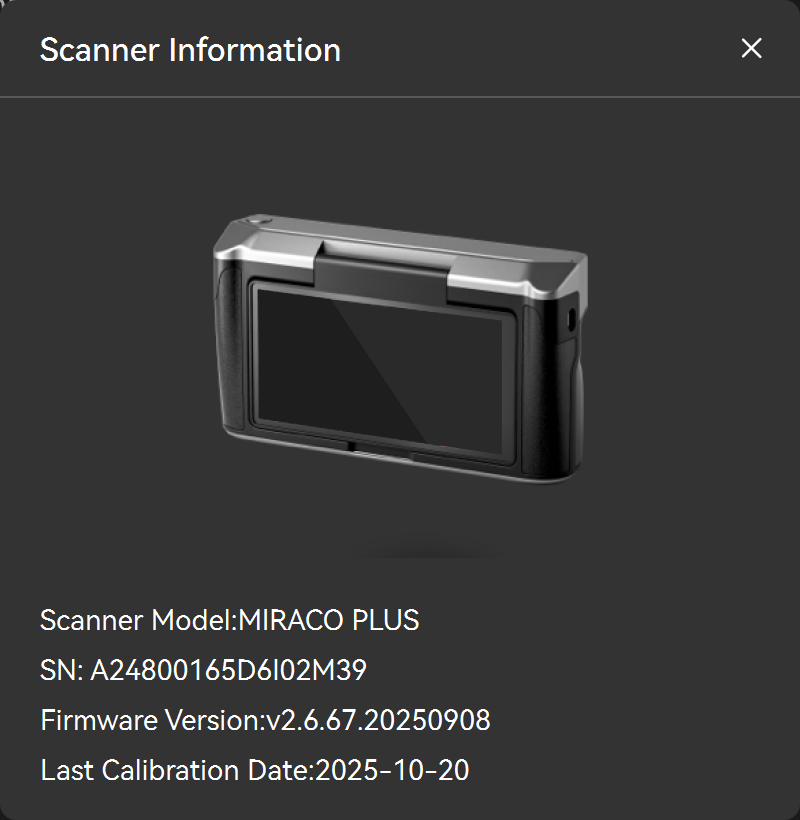
Click the "Scanner Information" in the menu bar at the top of the scan interface to get the basic information of the currently connected scanner, including the device model, SN code, firmware version number, and the last calibration date.
¶ 4.8 Mirroring & Fullscreen
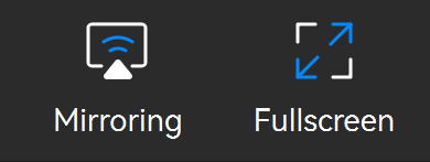
Mirroring: Supports mirroring the computer screen to a mobile device via Revo Mirror, enabling real-time preview and control of the scanning process. For detailed operations, refer to the Revo Mirror User Manual.
Fullscreen: Click the Full Screen button to enter full-screen preview. Reclick or use the shortcut Shift + M to exit full-screen display.
¶ 4.9 Camera Settings
¶ 4.9.1 Depth Camera
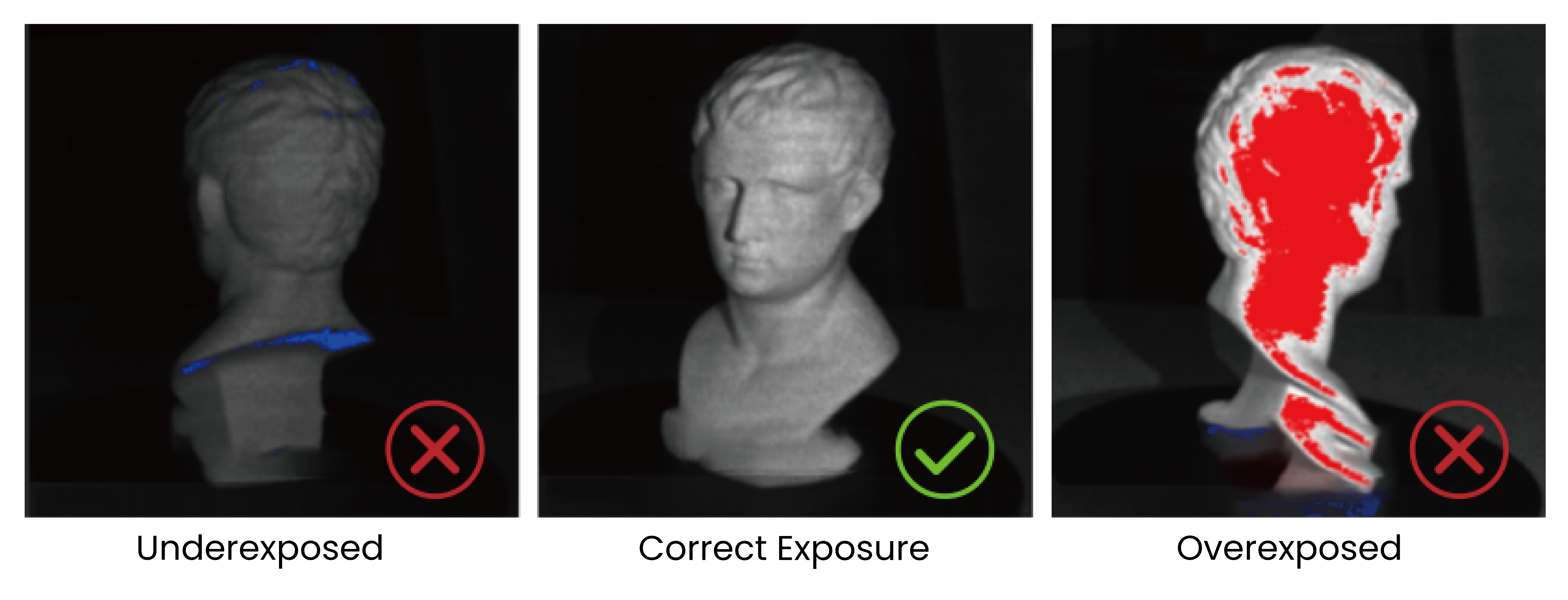
Adjusting the depth cameras' exposure before starting a scan is crucial to getting a good 3D model.
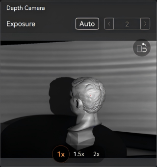
- Adjusting Exposure
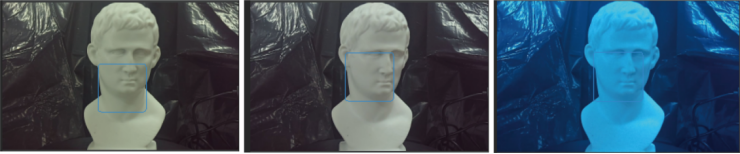
Click the Auto button to enable auto exposure. Click it again to disable auto exposure and then drag the slider to manually adjust the exposure value. To ensure scanning accuracy, adjust the exposure to minimize red or blue areas on the surface of the object being scanned.
- Digital Zoom
The digital zoom feature allows you to focus and enlarge smaller objects during scanning, giving you a clearer view of how the scan is progressing across the object's surface.
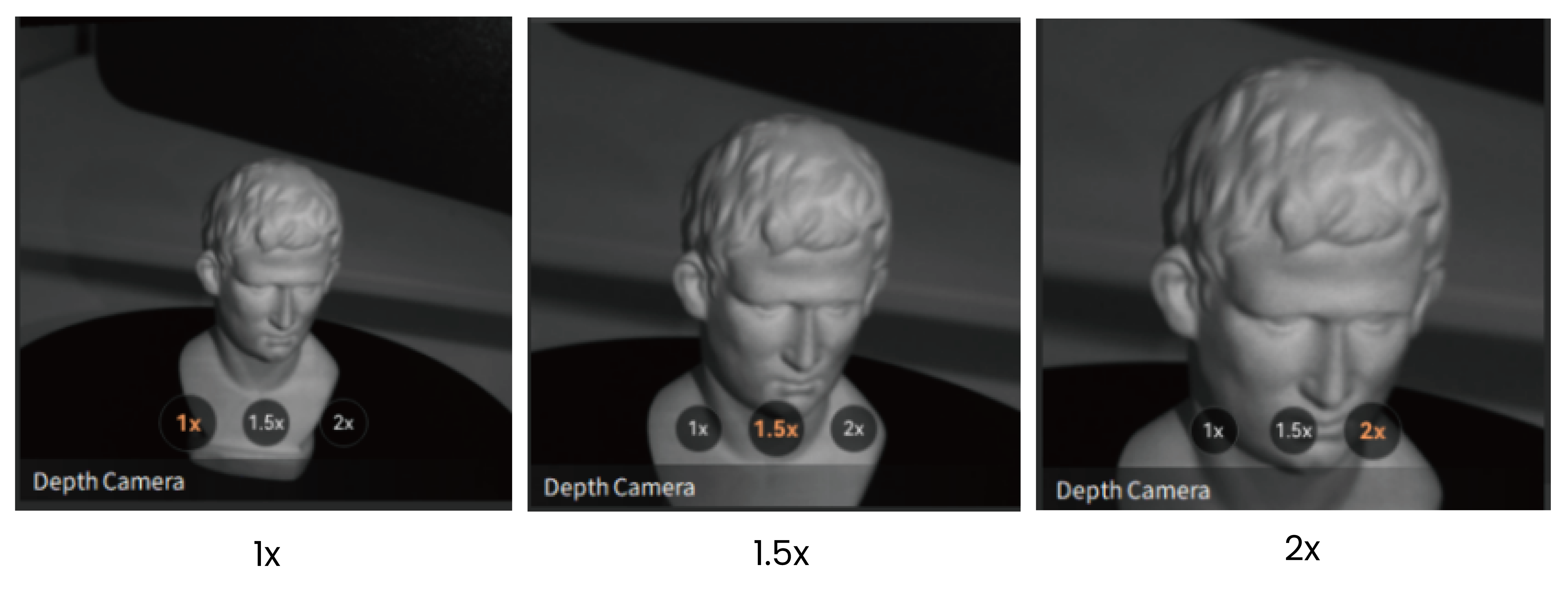
- Optical zoom (supported only on MIRACO Plus/POP 3 Plus scanners)
For smaller objects, the optical zoom function offers up to 1.5X/2X magnification to capture surface details more clearly during scanning.
When using Laser Lines scanning mode, the depth camera window is as follows:
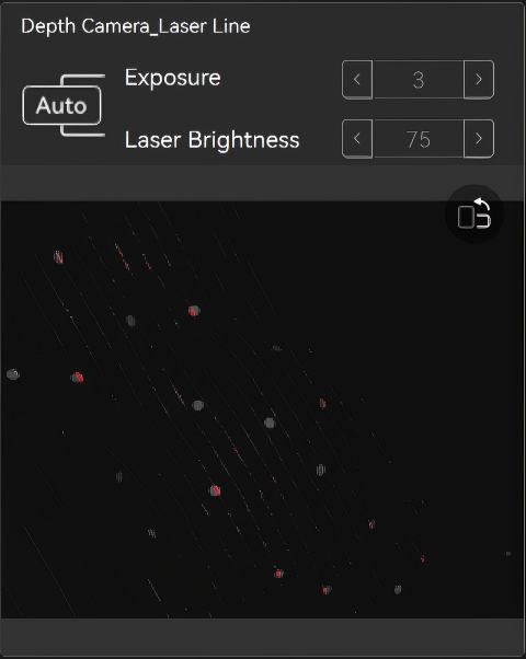
- Depth Camera Exposure
The exposure of the depth camera can be set to automatic exposure or manually adjusted. It's recommended to use the default values. When manually adjusting the exposure in laser scanning modes, ensure that the object color in the depth camera preview window is gray.
- Laser Brightness
It's recommended that you use the default value to avoid affecting the scan's results.
Note: When the scanning starts, the camera preview window will be automatically hidden. You can manually click the x button in the upper-right corner of the preview window to make it displayed.
¶ 4.9.2 RGB Camera
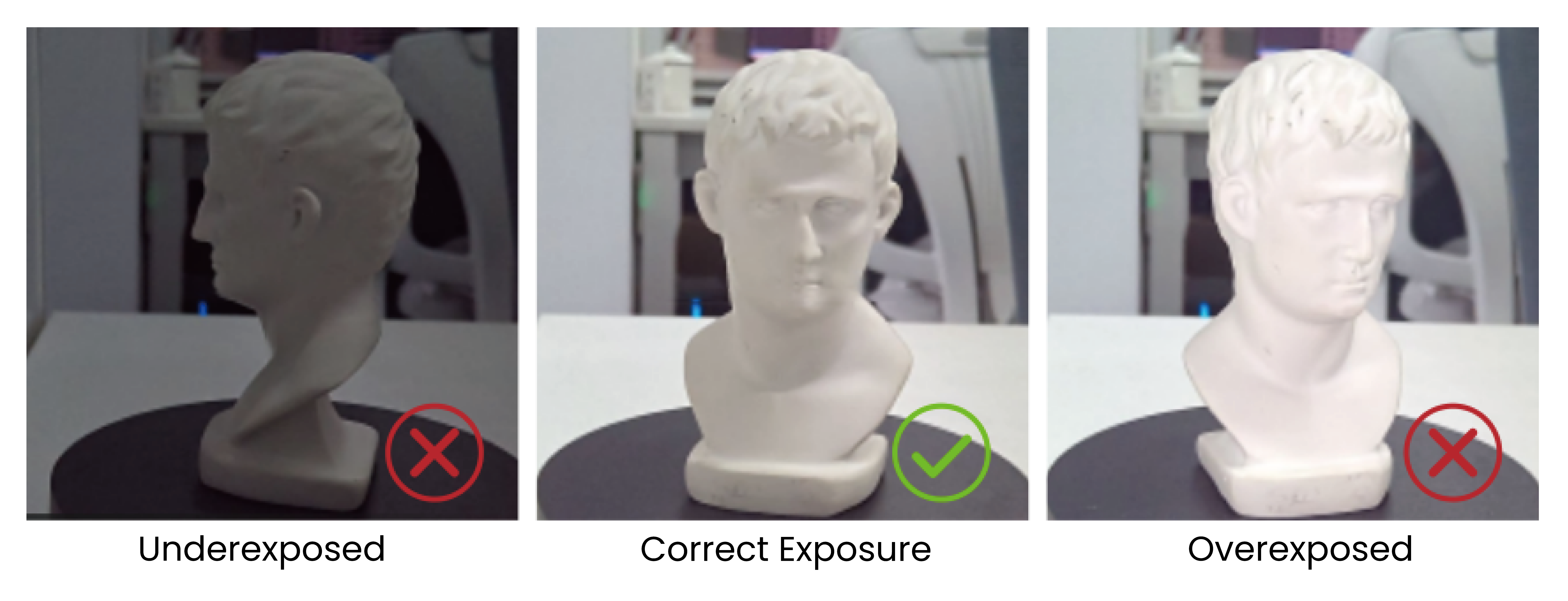
To capture an object's color accurately during a scan, please ensure it is evenly lit with soft light, and the RGB camera's exposure and white balance have been adjusted.
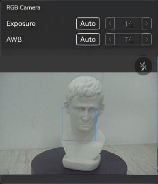
- Adjusting Exposure
Click the Auto button to turn on automatic exposure, or click it again to turn off automatic exposure and use the slider to manually adjust the exposure setting.
- White Balance
Click the Auto button to turn on automatic white balance, or turn off automatic white balance and use the slider to manually adjust the white balance until the colors look true to the actual object, ensuring they are neither too warm nor too cool.
- Fill light
The RGB camera's fill light can be enabled to improve color scanning results or increase marker point visibility. (Only available for scanners equipped with built-in fill lights)
¶ 4.10 Scanning Distance Indicator Bar
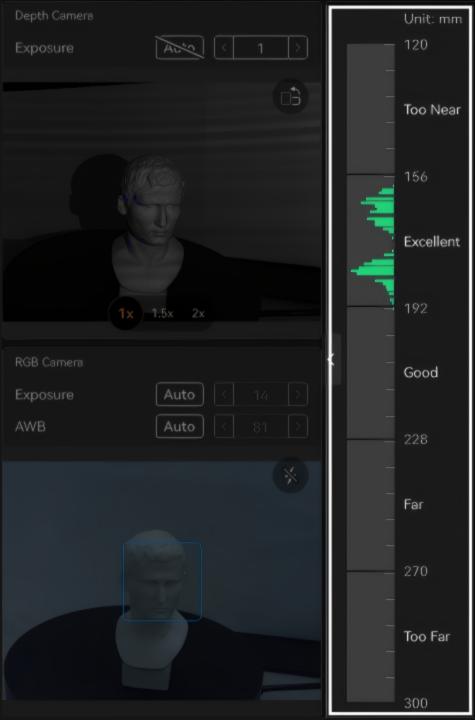
Adjust the scanning distance before a new scan. The distance indicator bar shows the distance between the object and the scanner. It's suggested to keep the bar green (optimal) when scanning.
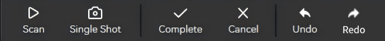
¶ 4.11 Scanning Controls
 /
/ : Click to start or pause the scan. The scanner continuously tracks the object, capturing its surface and fine details. After the scan is completed, if you need to improve the model, return to the Scan interface and click
  Preview button to continue scanning.
 : Each press of the "Start" button captures a frame using the scanner. During single-shot scanning, the point cloud overlap between consecutive frames must be at least 50% to ensure successful registration. Single Shot Scanning Tutorial (For reference only)
 : Click here to end the scan and proceed to the model editing interface.
 : Click to cancel the scan.
 /
/ : While paused, click to undo (Ctrl+Z) or redo (Ctrl+Y) scan data adjustments.
¶ 5. Model Editing
Model editing offers both One-click Edit and Manual Editing modes. One-click Edit provides quick results, while manual editing offers higher flexibility for high-quality outputs.
¶ 5.1 One-click Edit
Revo Scan 6 has a powerful One-click editing feature that can automatically process the model or allow manual parameter adjustment for point cloud editing and mesh editing.
Click "Apply" or "One-click Edit" icon to perform the relevant operations.
Note: The “One-click Edit” function is recommended for the first few scans.
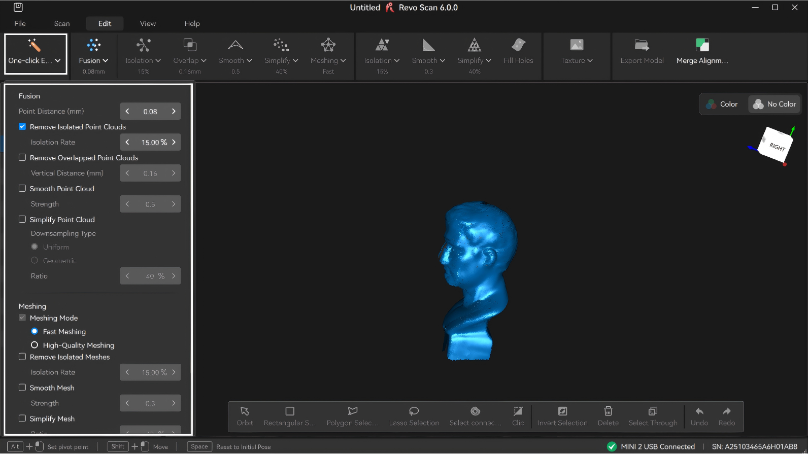
¶ 5.2 Point Cloud Edit
Point cloud processing helps clean up and refine the raw scan data, performing operations like point cloud fusion and removing isolated points, to produce a high-quality base point cloud for later meshing and model creation.
¶ 5.2.1 Fusion
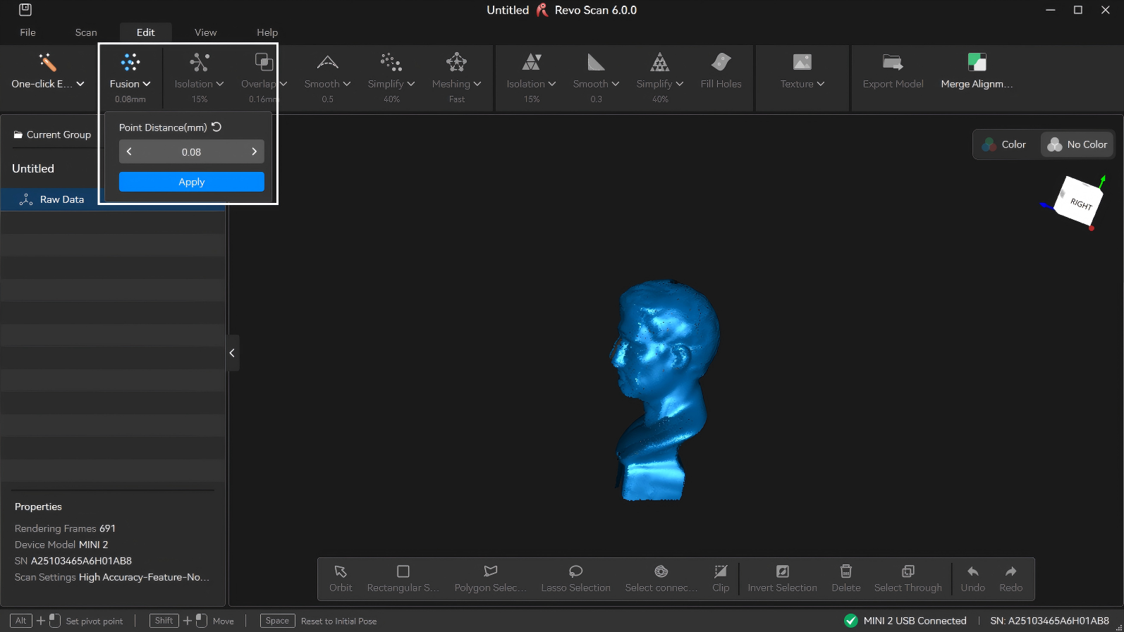
Fusion is fusing the raw scan data captured by the scanner into a unified point cloud model.
• Point Distance: The average distance between the adjacent points in a fused model. Revo Scan 6 will suggest an optimal point distance for each scan, but different values can be specified depending on your requirements.
Larger point distance results in fewer model details, while smaller point distance produces more model details but also increases data volume.
Note: If model merging is required, it is recommended to maintain similar point spacing across all models when configuring their respective point spacing settings to enhance the merging effect.
• Remove Marker (Marker/Global Marker Scan): After starting this function and selecting the inner diameter of the corresponding pasted markers, the software will automatically detect and remove the raised point clouds on the model surface caused by the occlusion of the markers. The larger the inner diameter of the markers is, the larger the hole left after removal.
Note: The imported Revo Scan 5 files only support selecting markers of size 6 mm.
• Marker removal offset (mm): Adjusts the removal area based on the default marker removal diameter to prevent residual marker edges from affecting scan data.
After setting the point distance, click "Apply" or "Fusion" icon to perform the Fusion function.
¶ 5.2.2 Point Cloud Isolation
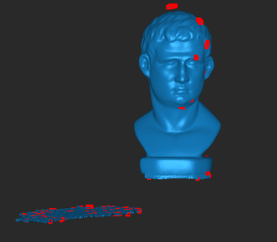
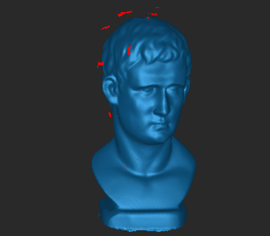
Click the drop-down button to detect and remove the isolated point cloud data disconnected from the main point cloud model (see the red area in the figure).
Isolation Rate: The percentage of points within isolated point clouds relative to the total number of points. Setting a higher rate will detect more isolated point clouds.
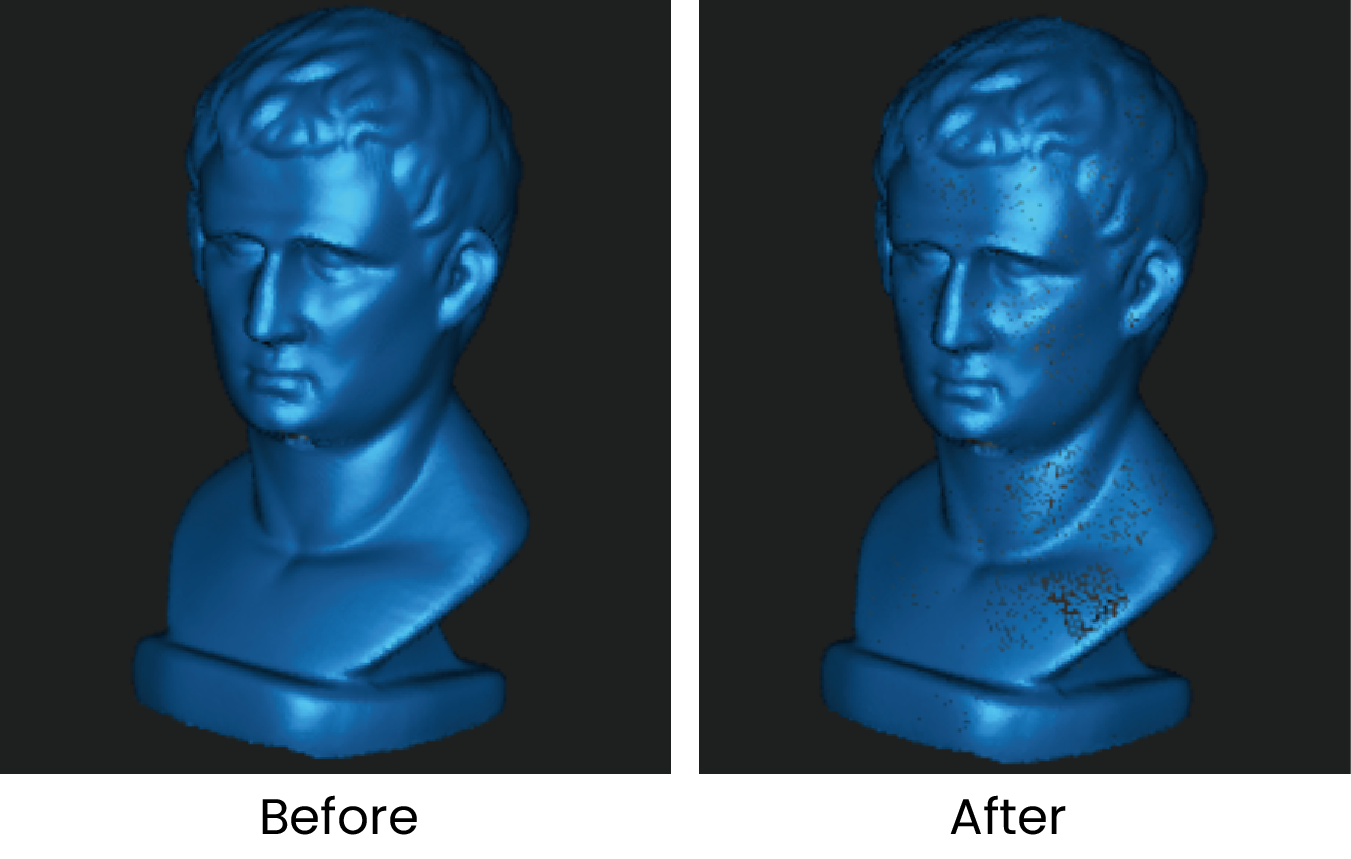
¶ 5.2.3 Point Cloud Overlap Detection

Click the drop-down button to identify and delete overlapping data in the point cloud for a more consistent model. It can be used repeatedly to simplify point cloud data.
Vertical Distance: The distance between the overlapped point cloud noise and the captured surface area. If it's less than the set value, it's considered noise and removed. If it exceeds the set value, it's not removed.
¶ 5.2.4 Point Cloud Smooth
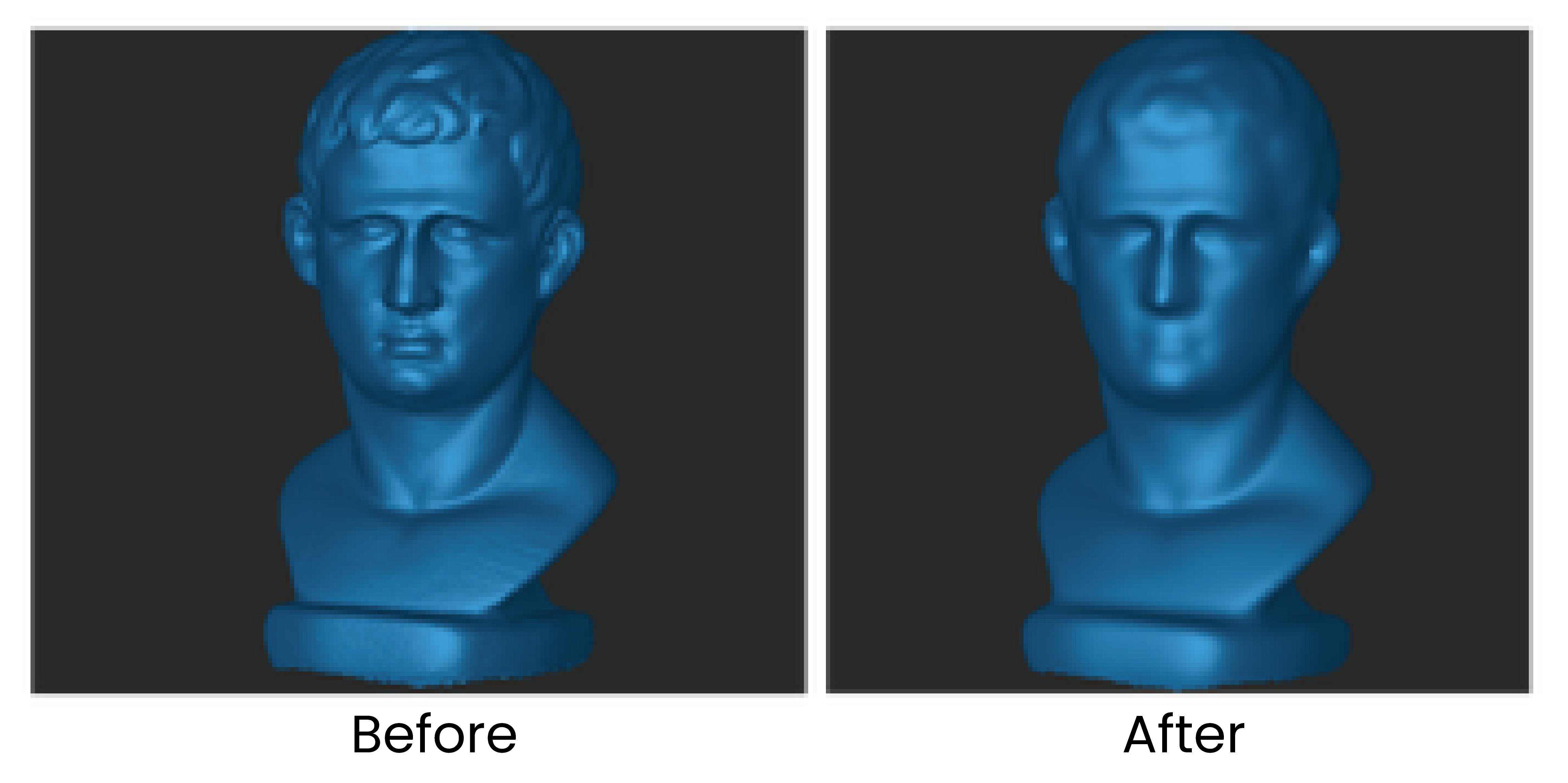
Removes noise from the point cloud to make it smoother.
A higher smoothing strength results in a smoother point cloud but may lead to the loss of more details.
Note: For feature-rich models, excessive smoothing may result in loss of details (see the figure below).
¶ 5.2.5 Point Cloud Simplify
Reduces the density of the point cloud and the amount of data for more manageable processing, storage, and sharing. There are two different downsampling methods:
• Uniform: Removes the set percentage of points across the model evenly.
• Geometric: Intelligently identifies flat or plain surfaces in the point cloud and will remove the set percentage of points from these areas while leaving more complex areas alone to maintain the details.
Ratio: The percentage of simplified point cloud data to the total amount of data. Setting a higher ratio will delete more point cloud data from the model.
Note: Selecting a too high ratio may impact the model's quality.
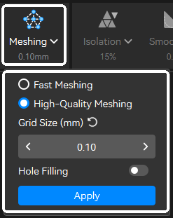
¶ 5.2.6 Mesh
Meshing converts the discrete point cloud data into a continuous surface mesh by connecting points into triangular polygons. Two meshing methods are available:
• Fast Meshing: The software recommends parameters based on the point distance calculation and performs triangulation on point cloud data to quickly generate a mesh model. Ideal for scenarios where a quick preview of the mesh is needed.
• High-quality Meshing: It performs triangulation on point cloud data using custom quality settings to generate a mesh model.
① Grid Size: The mesh model's density and level of detail. A smaller value produces a finer, more detailed mesh but takes longer to process.
② Hole Filling (Auto): Revo Scan 6 automatically identifies and fills holes on the mesh model.
Note: The Hole Filling (Auto) function is for small holes. Use the manual hole-filling tool in the mesh editing tab to fill larger holes.
¶ 5.3 Mesh Edit
The mesh processing page allows further optimization of the initial mesh generated from the point cloud, enhancing the model’s structure and surface quality, with support for texture mapping.
¶ 5.3.1 Mesh Isolation
Click the drop-down button to detect and remove the isolated mesh data disconnected from the main mesh.
Isolation Rate: The percentage of an isolated mesh relative to the total number of meshes. Setting a higher value will detect more isolated mesh data.
¶ 5.3.2 Mesh Smooth
Removes noise from the mesh model to make it smoother.
A higher smoothing strength results in a smoother point cloud but may lead to the loss of more details.
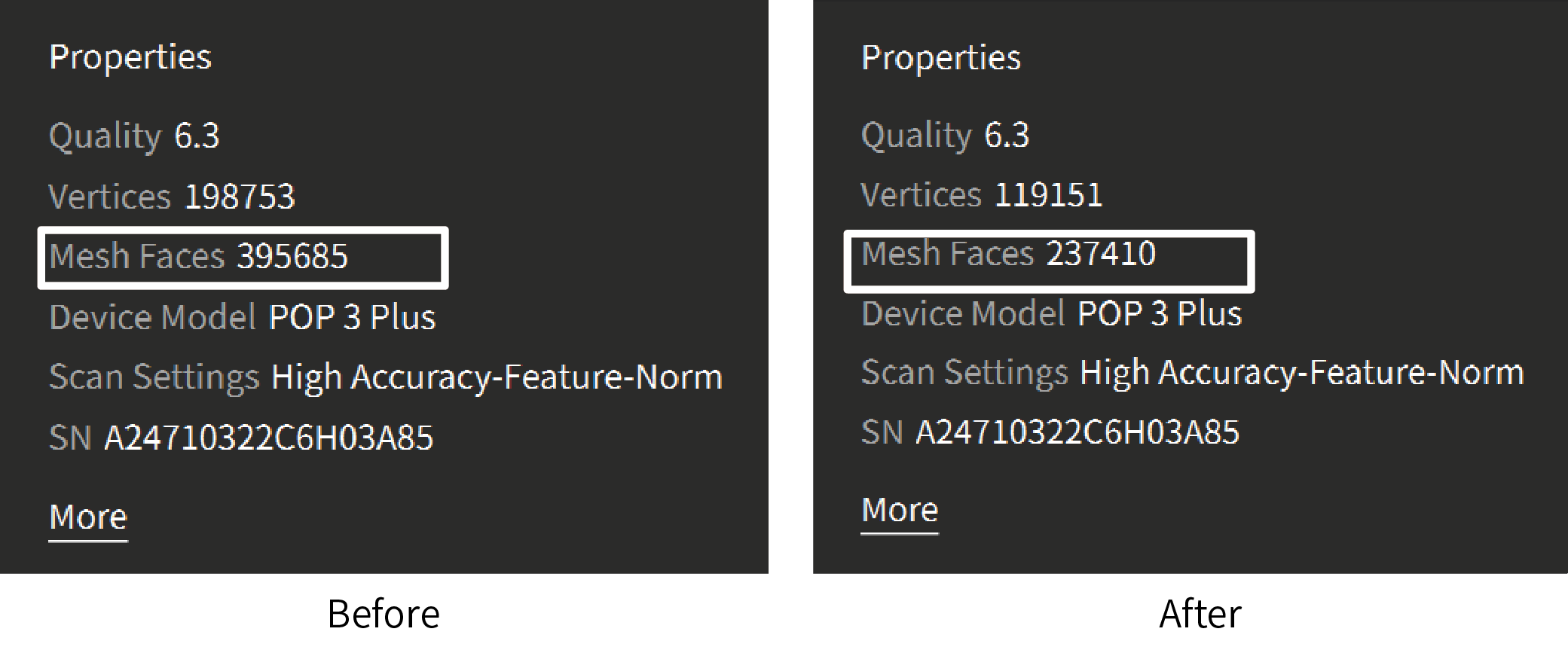
¶ 5.3.3 Mesh Simplify
Reduces the mesh data in the model for more manageable processing, storage, and sharing.
Ratio: The percentage of simplified mesh data to the total data volume. Setting a higher ratio will remove more details, resulting in a smaller file size.
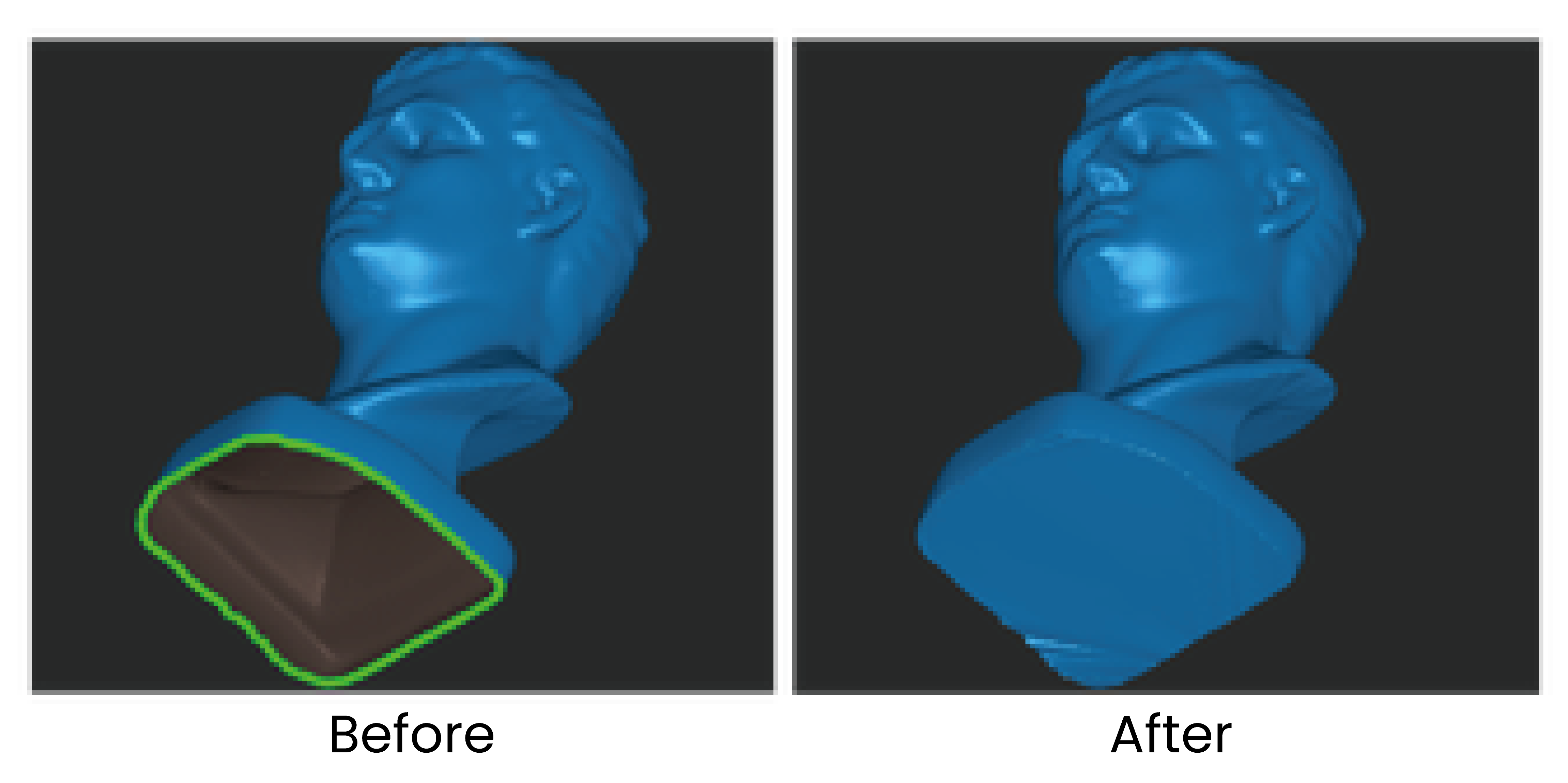
¶ 5.3.4 Fill Holes
Detects all holes on the model surface. Select the holes by clicking their edges, then choose either the Plane or Curved method to fill them (Multiple holes can be selected using the selection tool at the bottom of the interface).
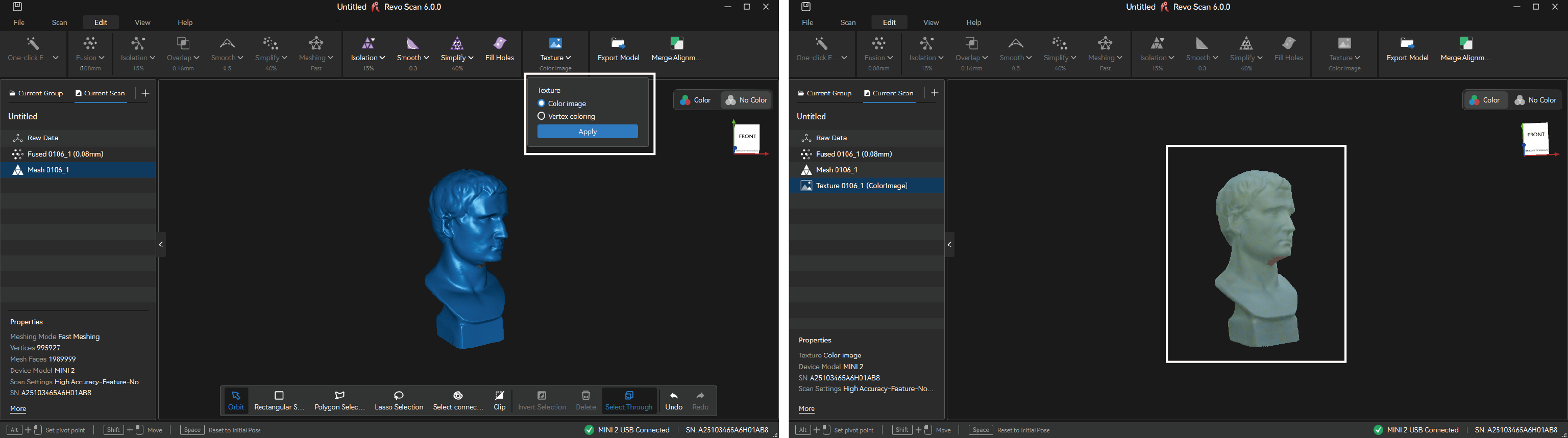
¶ 5.4 Texture
If color scanning was enabled in the scan settings, texture mapping can then be applied to the mesh model. Texture is applying the color data captured by the RGB camera to the mesh to create a high-quality colored 3D model. There are two texturing methods:
• Color Image
This method maps the image data captured by the scanner's RGB Camera on the mesh's surface to create a colored model.
• Vertex Coloring
This method generates textures from the mesh's vertices color.
Click "Apply" or "Texture" button to perform the texture function.
¶ 5.5 3DGS (POP 4 Only)
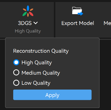
Using scaled Gaussian splatter 3D modeling reconstruction, the point cloud and RGB scan data are converted into a 1:1 realistic Gaussian model, enhancing realism while maintaining accuracy.
To use the 3DGS feature, enable "Color Scanning" before scanning to capture RGB images (Color Scanning is enabled by default when using Color Tracking mode). For optimal 3DGS reconstruction results, keep the scanner steady throughout the scan and minimise sudden movements. Capture the object from multiple angles whenever possible to ensure complete coverage, and collect a sufficient number of color image frames to fully record surface details.
3DGS is available only after meshing has been completed. Select the desired Reconstruction Quality based on your application requirements and available GPU performance. The reconstructed model can be exported in *.splat and other supported file formats.
Note: On Windows, this feature currently supports NVIDIA GPUs only. The minimum GPU memory requirements for each reconstruction quality level are as follows: Low Quality (4 GB or higher), Medium Quality (6 GB or higher), and High Quality (8 GB or higher). Higher reconstruction quality settings require greater GPU performance and longer processing times.
How to Import 3DGS Files into 3D Content Creation Software Using Plugins
¶ 5.6 Tool Bar
The Toolbar provides multiple tools for manually selecting unwanted local data for detailed editing or deletion.
Note: The Tool Bar can't be used for raw data or textured models.
Tool Bar Usage Tutorial (For reference only)
 |
Orbit(Shortcut key: V) Rotate the view in any direction. Clicking it will also de-select any previously selected areas. |
 |
Rectangular Selection(Shortcut key: M) Click and hold the left mouse button to draw a rectangle around any point on the model to select that area. |
 |
Polygon Selection(Shortcut key: L) Left-click to create anchor points to select a mesh's polygons (faces). The Polygon tool creates a straight line between each Anchor Point. Click on any edge of the area to be selected and release the mouse pointer to make an Anchor Point. |
 |
Lasso Selection(Shortcut key: U) Click and hold the left mouse button, then draw a shape around an area to select it. Release the mouse button, and the selection will be closed by connecting the current pointer location to the start location with a line. |
 |
Select Connection(Shortcut key: B) Left-click on a point or a data area, and the tool will automatically select the adjacent or connected points or areas. |
 |
Clip(Shortcut key: C) Position the cursor, click and hold the left mouse button, and drag. The clipping plane will appear as a line with an arrow. The portion of the model in the direction of the line's arrow will be selected. PressDeleteto apply the change,Escto cancel. |
 |
Invert Selection(Shortcut key: Ctrl+Shift+I) Use the invert selection button to change the selected area from the currently selected area to anything that wasn't selected. |
 |
Delete(Shortcut key: Delete) Click to delete the selected data. Or click Delete to also delete the selected data. |
 |
Select Through(Shortcut key: Ctrl+Shift+T) Used with Polygon Selection, Lasso Selection, etc. Enable it to select data right through the model. |
|
|
Undo(Shortcut key: Ctrl+Z) Used to remove the scan data or revert the changes made to the model. |
|
|
Redo(Shortcut key: Ctrl+Y) Used to add back the scan data or the changes made to the model. |
¶ 5.7 Alignment
The merging function supports the alignment of multiple scans in a project into a new model. Please note that the scans can only be merged after they are fused. Users can enter Merge Alignment through the following two methods:
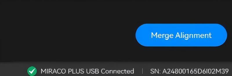
① On the "File" interface, click the "Merge Alignment" button in the lower right corner to enter the model merging interface. Choose a proper merge method, then select the models on the left to start merging.
② Users can also group scan files on the "File" interface. Within a group, click the "Merge Alignment" button at the lower right corner to open the merging interface. Choose a merge method and select the models in that group to complete the merge.
The model merging process supports two alignment methods: Manual Alignment and Feature Alignment.
¶ 5.7.1 Manual Alignment
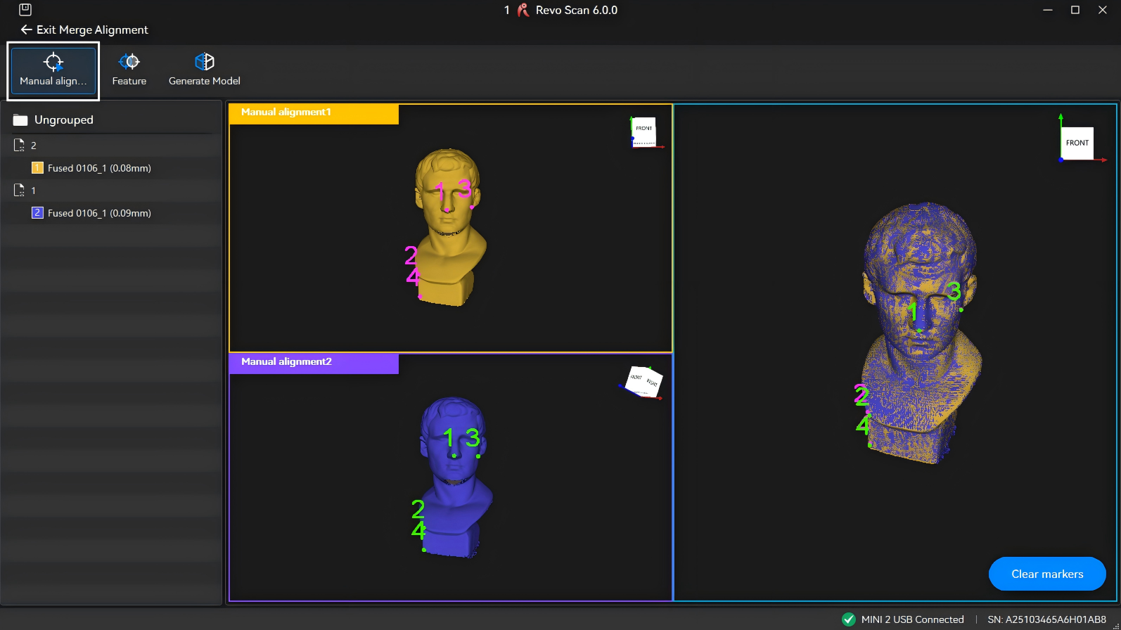
Manually mark 3 or more corresponding points at the same locations on both models. The system aligns models by analyzing the relative positions of these overlapping points. Only two models can be merged at a time.
- The number of marked points on both models must be identical and at least three pairs.
- Points on the same model should be evenly distributed with sufficient spacing between them.
- To place markers accurately, zoom in on the model by rolling the mouse wheel while hovering over it.
After completing point marking, click Generate Model icon to start the merging process.
¶ 5.7.2 Feature Alignment
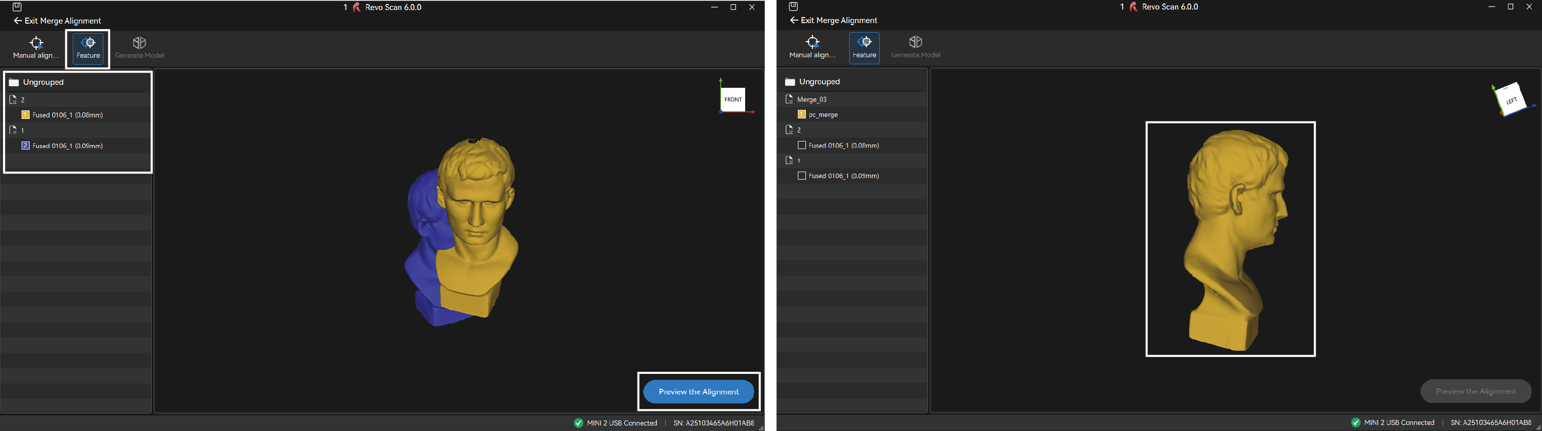
Select the models to merge. The system automatically identifies overlapping features to align them. Requirements:
- The overlap area between any two models must be at least 10%.
- For optimal results, maintain an overlap area of 40%-50%.
- Up to 9 models can be selected for alignment in a single operation.
You can first click Preview Alignment to inspect the merging result visually. After confirmation, click Generate Model icon to proceed with merging.
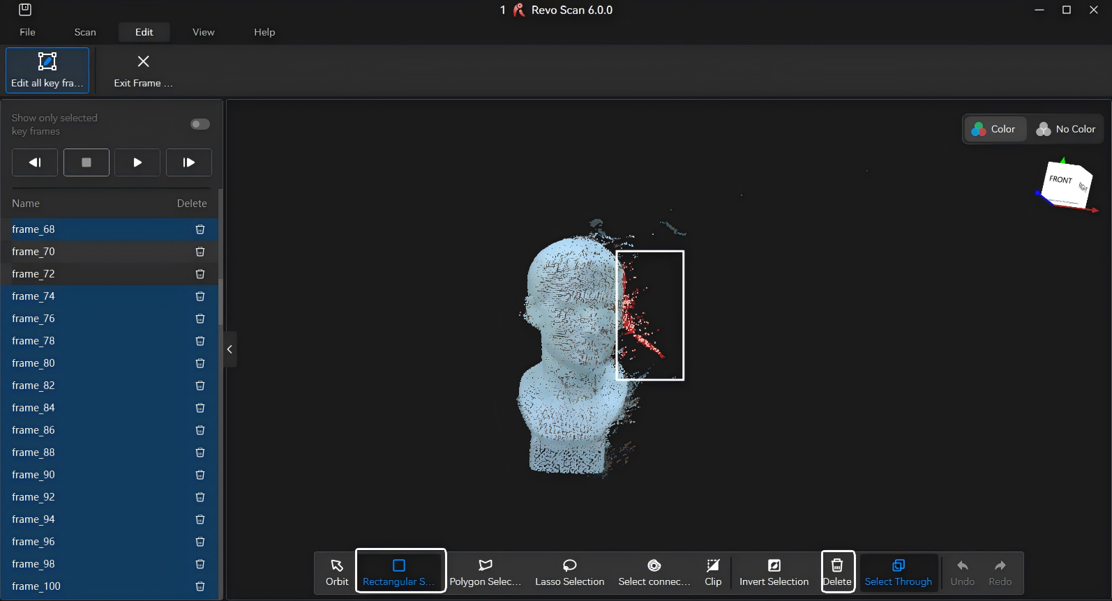
¶ 5.8 Key Frames Edit
Use it to edit or delete the raw data before fusion. This tool can be used to go through captured point cloud data frame-by-frame and quickly find the misaligned or faulty frame for deletion.
Key Frames Edit Tutorial Video (For reference only)
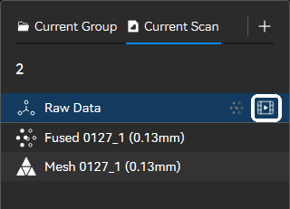 |
Click the  icon next to the Raw Data model in the list to enter the keyframe editing interface. There are two methods for keyframe editing: icon next to the Raw Data model in the list to enter the keyframe editing interface. There are two methods for keyframe editing: |
1) Click the  button to autoplay through the frames individually. Then, select any unwanted frames and click the
  button next to each frame's name.
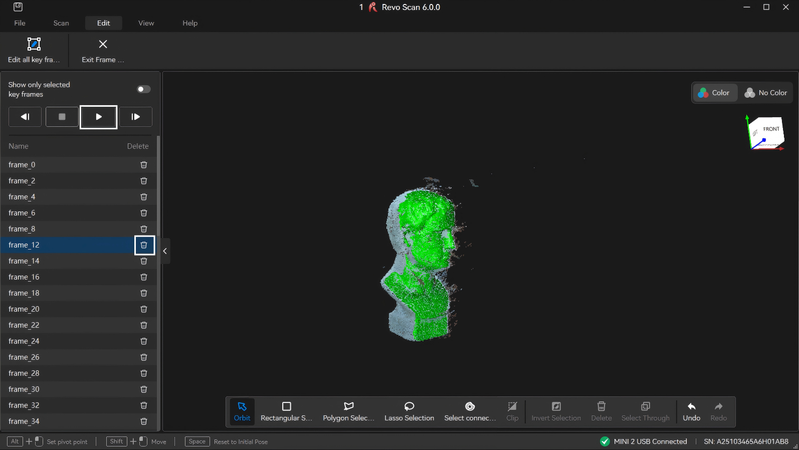
2) In the Key Frames Edit interface, use the selection tools in the bottom toolbar to select any unwanted data on the model. The software will automatically detect the selected data. Then click the "Delete" button to remove it (To delete multiple scan frames, click and drag vertically in the list to select them).
¶ 5.9 View
- 3D Projection View
Perspective View: The camera is positioned at a fixed point in space, so the model has a sense of depth and distance. This is the default view.
Orthogonal View: All objects appear at the same scale, and all three dimensions (width, height, and depth) are projected onto a 2D plane to preserve their relative sizes and positions.
- Show Reverse Point
Shows or hides the surface across from the current one in another color (brown or transparent).
- Mesh Model Display
The mesh model can be displayed in three forms: solid, wireframe, or wireframe overlay.
- Default Position
Shows the 3D model from a viewpoint determined by the first few frames captured.
- Show Bounding Box
Displays or hides the bounding box around the current model. The bounding box is a rectangular box that is wrapped as tightly as possible around the object.
- Show Rotation Ball
Displays the XYZ rotation axis to show the model's orientation in 3D space.
- Show Grid
Displays or hides a virtual 3D grid in the editing interface. The grid is a structure of horizontal and vertical lines that help to position and align objects.
- Model Material Display
Click to change the model's color and surface properties.
¶ 5.10 Open with other software
Click the  icon next to the model and select "Open with other software" to import the model into Revo Design or Revo Measure for further processing and analysis.
¶ 6. Scanner Calibration
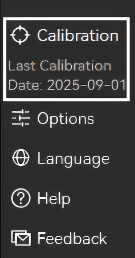
The scanner is professionally calibrated at the factory. Revo Scan 6 also provides a recalibration feature, allowing users to recalibrate the scanner to maintain optimal accuracy. It is recommended to perform an accuracy check before each scanning session. If the scanner does not pass the accuracy check, follow the on-screen instructions to complete the calibration process.
Note: Ensure the PC is connected to a power source before initiating scanner calibration.
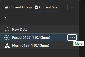
¶ 7. File Management
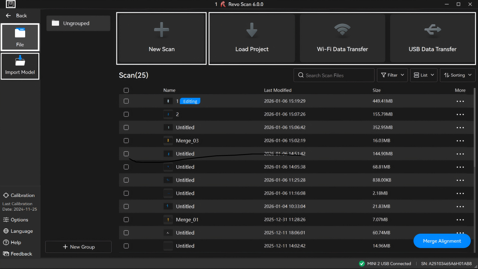
¶ 7.1 Create a New Scan
On the home page, wait for the scanner to connect. Click "New Scan". Select the desired tracking mode, name the scanning file, and then click "Confirm" to start the scan. You can also click the "  " icon above the model list on the left in the post-processing interface to create a new scan under the current group.
Revo Scan 6 allows you to create templates to quickly start a new scan. A template saves your previous scan and post-processing settings—such as camera exposure, scan accuracy, point spacing, and mesh quality. When a template is selected, these parameters are automatically applied to the new scan.
¶ 7.2 Save
Click the  icon at the top-left of the scan interface.
¶ 7.3 Import
Import models on the "File" interface.
- Local Import
- Click "Load Project" and select stored scan files on your PC for transfer.
- Wireless Import (Mobile Import/MIRACO Import)
1) Ensure the MIRACO/phone and PC are connected to the same Wi-Fi network.
2) On the "File" interface in Revo Scan 6 (PC), click "Wi-Fi". Select Revo Scan (mobile) or MIRACO for import, and use either the verification code or QR code transfer method to complete the import.
3) On the MIRACO/phone, select the target file from the scan list and click the bottom-right "More" > "Share Model".
4) Enter the PC's verification code or scan the computer's QR code to start file transfer.
- USB Import (MIRACO Import)
1) Use the MIRACO USB cable to connect the MIRACO device to the computer.
2) Select "File Transfer" in the pop-up window on the MIRACO interface.
3) Open Revo Scan 6 on the PC; the computer will display the MIRACO Project Files List shortly.
4) Select the required files and click the bottom-right button to save them to the computer.
Note: Do not minimize the application or turn off the phone screen during transfer, as this may cause failure.
- Import Model
Click “Import Model” and select the desired scan file.
- Drag and Drop Import
Quickly import external scan files by dragging them into the File interface.
Note:Supported formats include *.stl, *.obj, *.ply, *.revox . This method does not support Revo Scan 5 project files.
¶ 7.4 Export
The model can be exported at different processing stages using the "Export Model" button on the right side of the Edit bar.
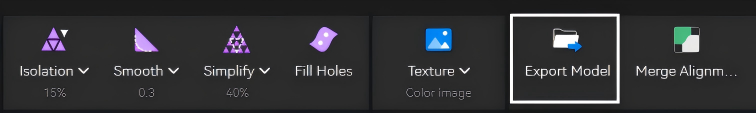
Alternatively, select a model from the list on the left, click the icon to choose the corresponding format to export.
¶ 8. First Scan
Revo Scan 6 includes a built-in onboarding guide to help users master basic operations during their first use.
Sections 8.1–8.3 use the MINI 2 and a sample statue to walk you through a complete scanning workflow with Revo Scan 6. For more advanced scanning techniques to improve scan quality, refer to Section 8.4.
The POP 4 scanner supports scan modes that differ slightly from other products. If using POP 4 for the first time, please refer to the POP 4 First Scan.
The overall scanning workflow is shown in the figure. Beginners are encouraged to follow the steps in parallel with hands-on practice:
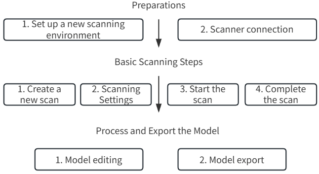
Note: The operational principles apply to other scanner models as well.
¶ 8.1 Preparation Phase
This section guides you through setting up the scanning environment and connecting the scanner, which are essential prerequisites before starting the scan. Ensure all steps are completed before proceeding.
¶ 8.1.1 Setting Up the Scanning Environment
1) Prepare the workspace: Ensure the scanning area is clean and free of clutter.
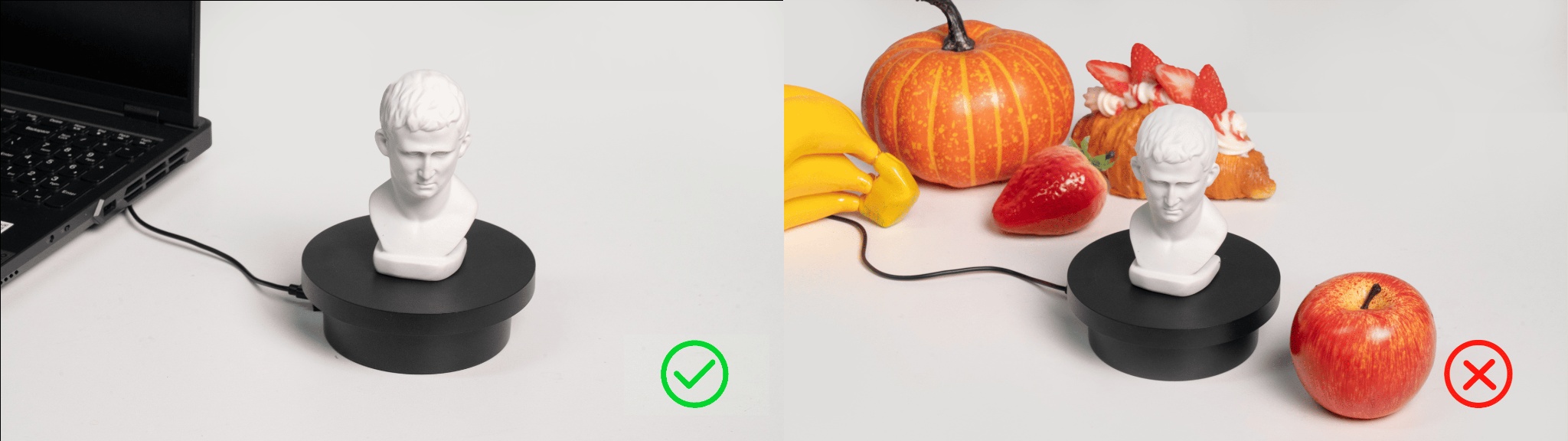
2) Connect the accessories: Use the turntable cable to connect the turntable to the computer port or power outlet, adjusting it to an appropriate rotation speed.
3) Check the object: Position the sample bust on the turntable, ensuring its surface is shadow-free.
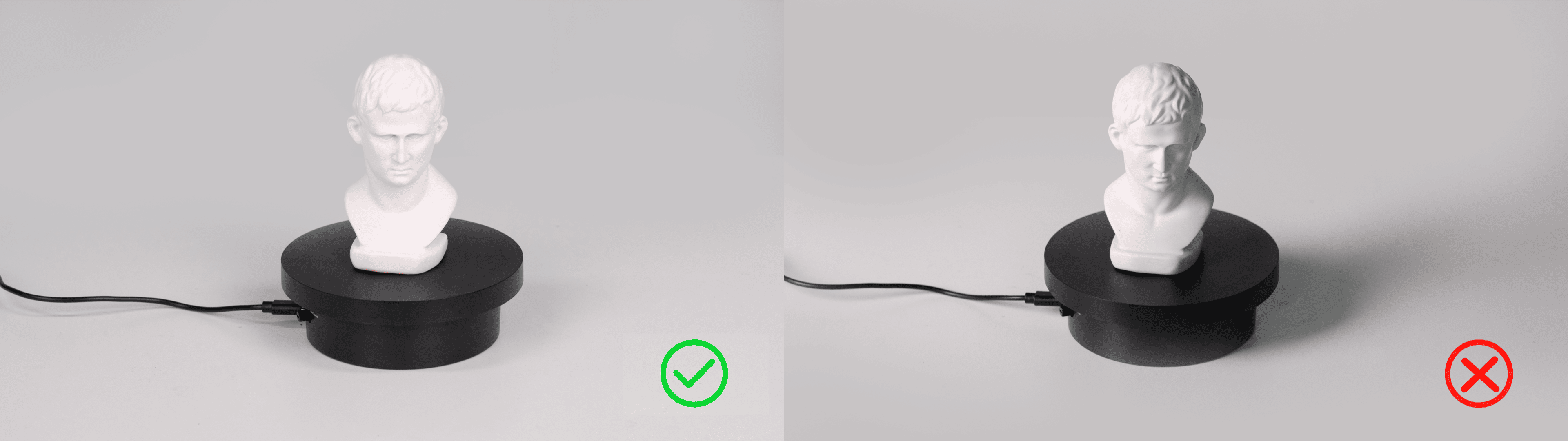
4) Adjust the scanner's height and angle to ensure the camera can fully capture the object.
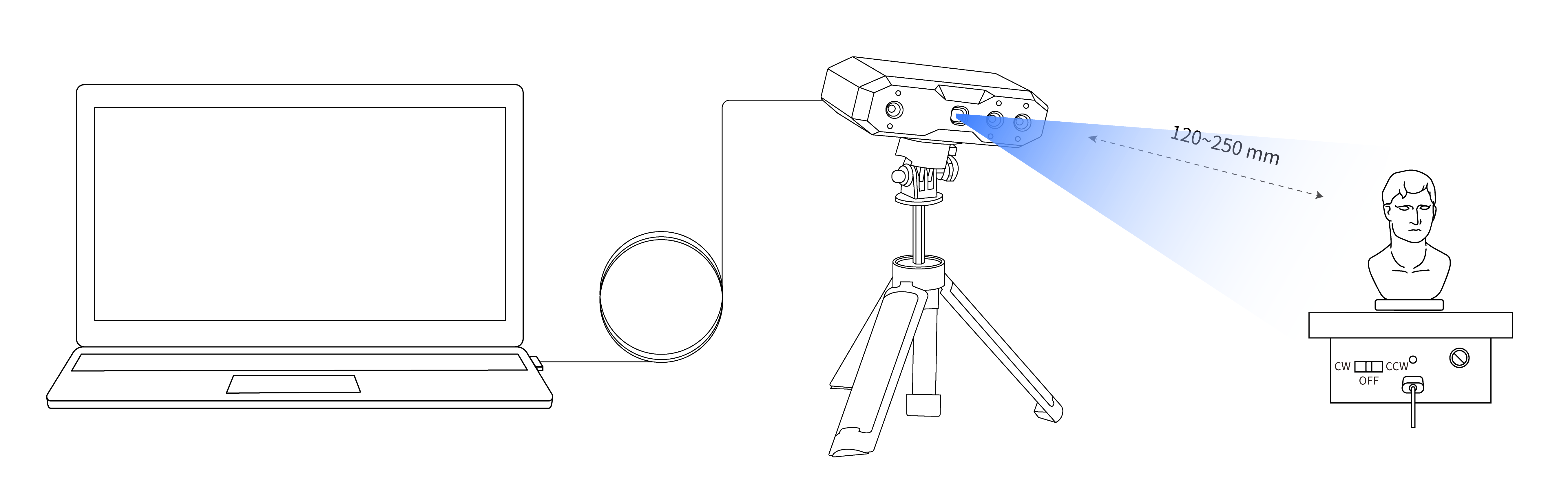
¶ 8.1.2 Scanner Connection
¶ 8.2 Basic Scanning Steps
This section outlines the fundamental steps for a standard scan, including creating a new scan, configuring parameters, initiating the scan, and finalizing it. Follow the sequence to ensure smooth operation.
¶ 8.2.1 Creating a New Scan
Open the software, and once the bottom-right corner shows that the scanner is connected, click "New Scan". Then choose "Feature" tracking mode to enter the scan interface.
¶ 8.2.2 Scan Settings
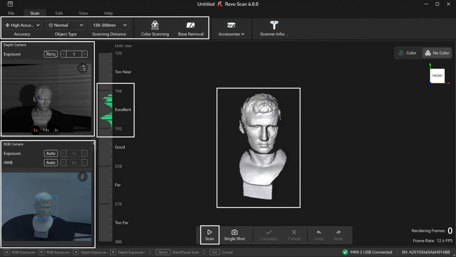
Optimal results require proper parameter settings, which affect model integrity, clarity, and post-processing efficiency. Refer to 4.2 Scan Parameters Settings for guidance on mode selection, accuracy levels, stitching methods, and object types. New users can refer to the following content to set parameters:
1) Check the model's position through the camera preview window on the left to ensure it is within the camera's field of view.
2) Select "High Accuracy", "Normal Objects". Adjust the scanning distance according to the requirements and choose whether to enable color scanning/base removal.
3) Adjust the distance between the scanner and the sample bust to ensure that the color on the distance indicator bar is displayed in green.
4) Adjust the exposure of the depth camera until the red or blue areas on the surface of the scanned object are reduced as much as possible. (Novice users are recommended to set it to automatic adjustment.)
¶ 8.2.3 Starting Scan
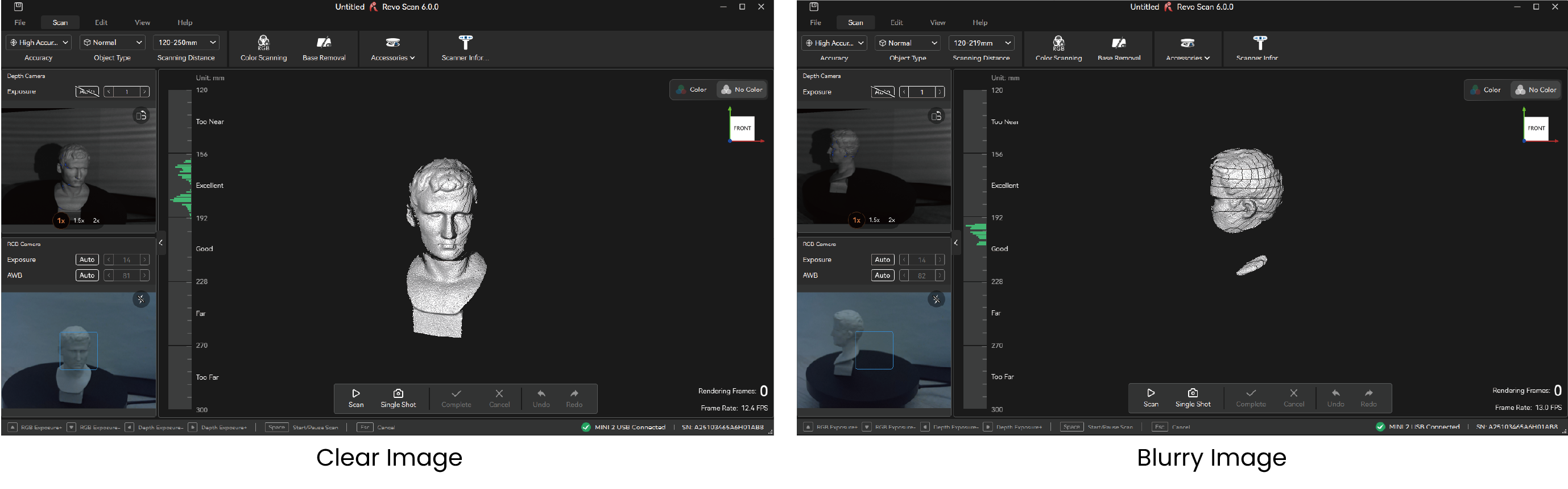
1) After setting these parameters, check the right-side distance indicator bar and object imaging. If the indicator bar shows green (optimal/good distance) and the object appears clear and complete, click "Start" to begin scanning. If the image is fragmented or blurry, review parameter settings or camera angles.
2) During scanning, pause to review progress in the model display area. If the model appears incomplete (as shown in the example), click "Start" again to continue.
Note: For hard-to-capture areas, pause the scan, reposition the object, and rescan to capture details. Avoid repeatedly scanning the same area to prevent stitching errors.
¶ 8.2.4 Finishing Scan
New users can use the following criteria to determine if scanning is complete:
1) Check if the model preview displays fully.
Ensure the real-time preview covers all surfaces of the target object, especially undersides, backsides, and crevices. (Small holes can be manually filled during post-processing.)
2) Check whether the model color/texture is uniform (if texturing is enabled).
If texturing is applied, check for obvious seams, missing color patches, or distortions.
3) Inspect point cloud/mesh for large gaps.
Pause scanning to check for unfilled areas or structural omissions in point cloud or preview models.
When the scan is completed, click the "Finish" button to end the scan. If the model still needs to be scanned again, you can return to the Scan interface, click the "Preview" button to continue scanning.
¶ 8.3 Model Processing & Export
This section explains basic post-scan model processing and exporting to common formats for further use.
¶ 8.3.1 Model Editing
Click "One-click Editing" icon to automatically complete the model editing. You can also manually adjust various parameters to complete model processing. In manual mode, sequentially refine the point cloud, mesh, and texture mapping. For detailed instructions, revisit 5.2 Point Cloud Edit and 5.3 Mesh Edit.
¶ 8.3.2 Model Export
After performing point cloud fusion, meshing, etc., click "Export" on the right side of the Edit bar and select the desired format for export.
For details on supported formats, applications and other information, visit 11.2 File Formats.
¶ 8.4 Scanning Tips
The preceding steps provide a foundational workflow. For enhanced results or efficiency, explore these advanced scanning tips:
2) Scanning Thin-Walled Objects
¶ 9. Option
Click the "Option" button on the side of the software to enter the software settings interface.
¶ 9.1 General
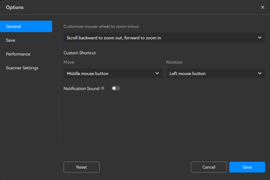
Customize Mouse Wheel Zoom Direction: Adjust the scrolling behavior of your mouse wheel to control zooming in/out orientation, allowing you to personalize how you scale content within the application.
Custom Keyboard Shortcuts: Design personalized keyboard combinations for commonly performed tasks, enabling faster execution and streamlining your workflow.
Notification Sound: Once enabled, the software will notify you when One-click Edit, Fusion, Meshing, and Texturing are complete.
¶ 9.2 Save
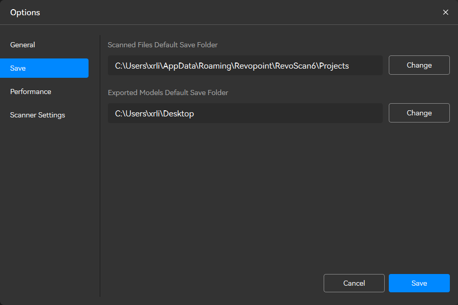
Scanned File Default Save Folder: Select the default file location for storing scans.
Exported Models Default Save Folder: Select the default file location for storing the model.
¶ 9.3 Performance
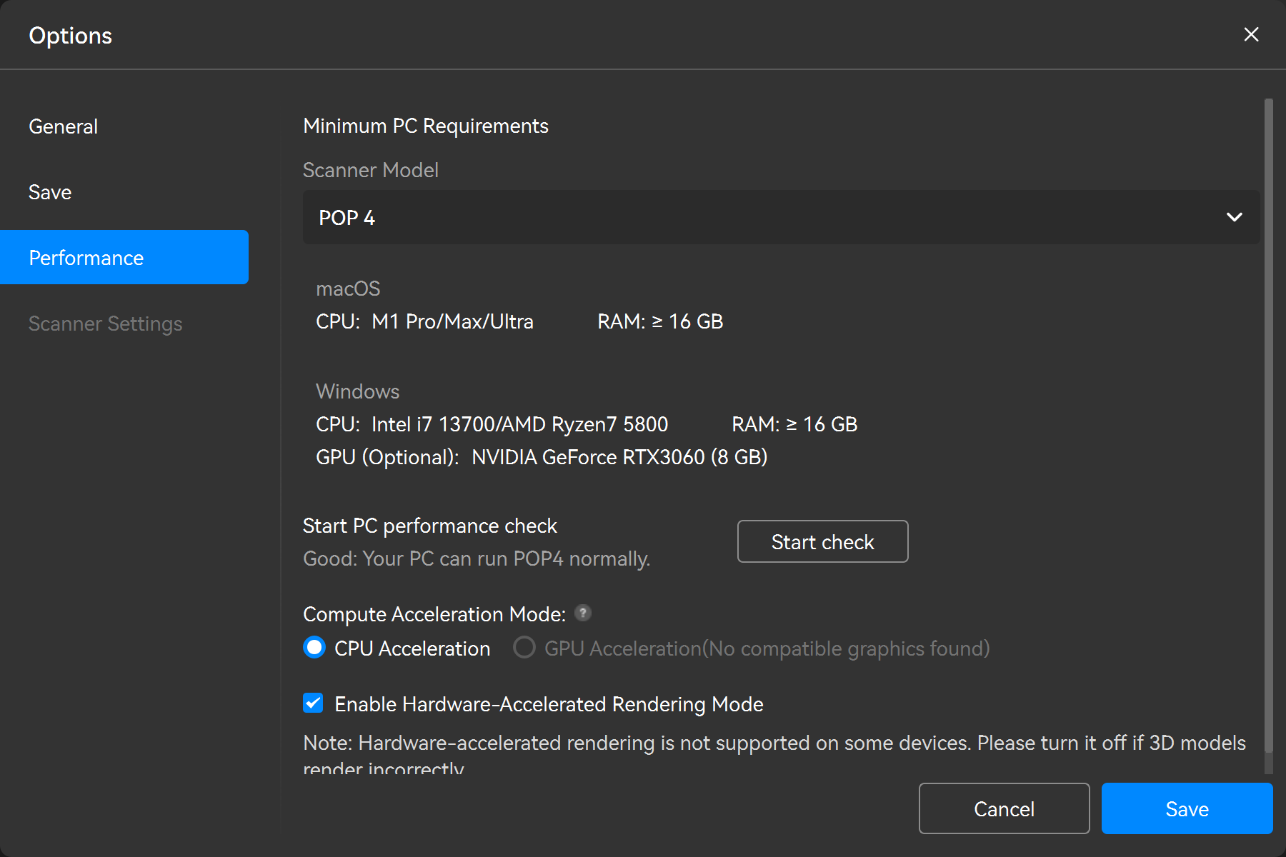
Minimum PC Requirements, PC Perform Check: Evaluate the computer's performance to determine if it can run Revo Scan 6 smoothly.
Compute Acceleration Mode: Supports CPU acceleration/GPU acceleration. Please select the acceleration mode appropriately to enhances frame rate stability and smoothness during the scan. It's recommended to use the suggested mode.
Enable Hardware-Accelerated Rendering Mode: This feature is enabled by default and is suitable for most computers. If you encounter rendering issues with 3D models during use, please uncheck the option here and then view the model again. (If your computer does not have a GPU, it is recommended to disable this function for a more stable experience.)
Note: GPU acceleration is only supported on the following models:
RTX 3050、RTX 3060、RTX 3060 Ti、RTX 3070、RTX 3070 Ti、RTX 3080、RTX 3080 Ti、RTX 3090、 RTX 4060、RTX 4060 Ti、RTX 4070、RTX 4070 Ti、RTX 4080、RTX 4090、RTX 2080 Super、RTX 2070 Super、RTX 2060 Super、RTX 3050 ADA
¶ 9.4 Scanner Settings
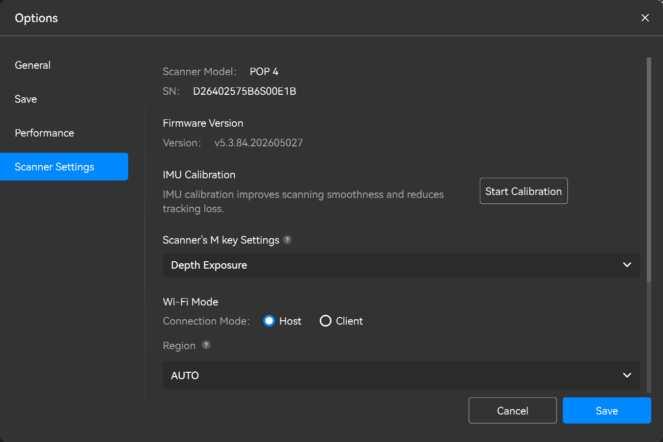
Scanner Info: See the scanner's type and serial number.
Firmware Version: An “Update” button will be displayed when a new firmware version is available. Click the button and follow the instructions to update.
IMU Calibration: The IMU sensor measures the scanner's acceleration, rotation, and orientation. Calibrating the IMU ensures the scanner tracks its movement data accurately, resulting in better frame stitching and scanning accuracy. Click the “Start Calibration” button and follow the onscreen instructions to complete the calibration process. IMU calibration only needs to be done when prompted by Revo Scan 6.
Scanner's M key Settings (POP 4 Only): The Scanner's M key can switch between the following functions: Zoom in/Zoom out Central Preview Window/Switch between lase line modes/Adjust the Depth Camera exposure/Adjust the laser brightness.
During a scan, short press the M key to quickly switch between those functions.
Note: This option will only appear if the connected scanner has an IMU.
|
|
|
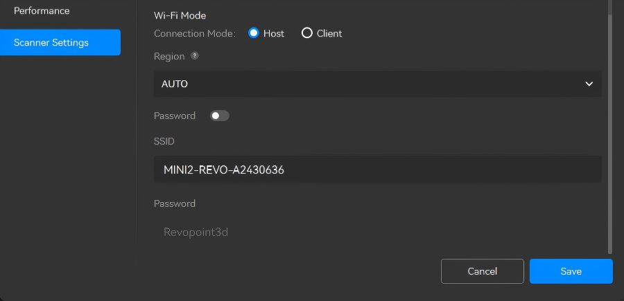
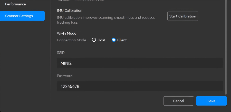
| Host | Client | |
| Operating Principle | Connect a scanner to a PC via the scanner's Wi-Fi. The PC will lose internet access via Wi-Fi. | Connect a scanner to a PC via a Wi-Fi network. Keep your PC connected to the internet. |
| How to connect? |
1. Find the "Scanner Name-REVO-XXXXXXX" Wi-Fi network and connect in PC Wi-Fi settings. 2. Open Revo Scan; the scanner connects shortly. |
1. Enter your Wi-Fi network SSID and password, then confirm. 2. Ensure the PC is on the same network, open Revo Scan and it connects shortly. |
| Notes |
1. If the scanner Wi-Fi is not found, switch your region in "Region", confirm, restart, and search again. 2. Remember the password if enabled, or Wi-Fi use will be blocked. |
Client mode is recommended only with a stable 5 GHz network. Keep scanner, PC, and router close. If network conditions are poor, use Host mode. |
¶ 10. Help & Feedback
¶ 10.1 Online Support
- If you have any questions about our products or software, please feel free to call our official customer service hotline +1 (888) 807-3339 or chat with one of our customer service agents online.
- Click the "Help" >"Online Support" in the bottom-left corner of the File interface to visit the Revopoint official website for more online services.
¶ 10.2 Feedback
If you encounter any problems while using the software, you can click "Feedback" at the lower left corner of the File interface to submit your problem description.
¶ 10.3 Social Media

¶ 11. Appendix
¶ 11.1 Glossary
¶ 11.2 File Format
¶ 11.3 Keyboard Shortcuts
| Function | Windows Shortcut | macOS Shortcut |
| Orbit (exit selection mode) |
V |
V |
| Rectangular Selection |
M |
M |
| Polygon Selection |
L |
L |
| Lasso Selection |
U |
U |
| Clip |
C |
C |
| Smooth Brush |
S |
S |
| Select All |
Ctrl+A |
Command+A |
| Invert Selection |
Ctrl+Shift+I |
Command+Shift+I |
| Delete |
Backspace |
Backspace |
| Undo |
Ctrl+Z |
Command+Z |
| Redo |
Ctrl+Y |
Command+Y |
| New Project |
Ctrl+N |
Command+N |
| Save |
Ctrl+S |
Command+S |
| Set Pivot Point |
Alt+Left-click |
Option+Left-click |
| Zoom In/Out |
Mouse Scroll Wheel or Two Fingered Pinch In & Out |
Mouse Scroll Wheel or Two Fingered Pinch In & Out |
| Move |
Shift+Left-click |
Shift+Left-click |
| Rotate in Selection Mode |
Ctrl+Left-click |
Command+Left-click |
| Zoom to Fit |
Ctrl+D |
Command+D |
| Default View |
Space |
Space |
| Select Through |
Ctrl+Shift+T |
Command+Shift+T |
| Select Connection |
B |
B |
| Reduce Selection |
Ctrl+Shift+Selection |
Command+Shift+Selection |