¶ 1.Welcome
Welcome to your Revopoint 3D scanner user manual! This manual provides Revo Metro's operation guide and instructions. Please read the manual before your first use. If needed, you can click on any topic in the navigation bar to quickly jump to that section.
Manual Download
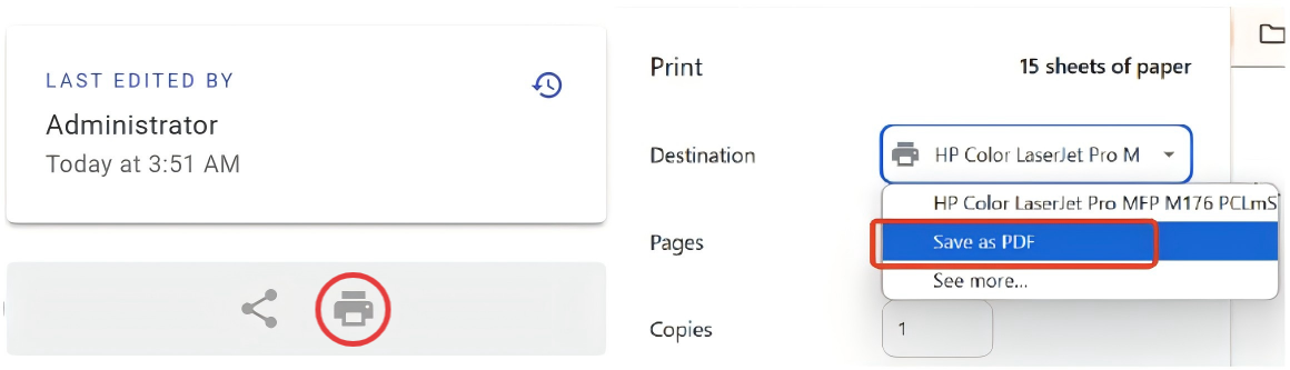
If you need a PDF manual, click the Print Format button at the bottom of the navigation bar on the left side of the manual, and select "Save as PDF" from the options.
- This manual is specifically for the MetroX Series 3D scanner, MetroY Serirs 3D scanner and INSPIRE 2 3D scanner. Some operations may differ depending on the scanner's model.
- This manual is frequently updated to cover the product's latest features and improvements.
¶ 2.Software Installation & Updates
¶ 2.1 System Requirements
| Minimum PC Requirements | |
|
Windows System Version: Windows 10/11 (64-bit) RAM: ≥ 32 GB CPU: Intel i7 13th Gen or AMD Ryzen 7 5800 GPU: NVIDIA GeForce RTX 3060 (8 GB) |
macOS System Version: macOS 11.0 or better RAM(MetroX): ≥ 16 GB RAM(MetroX Pro): ≥ 16 GB CPU (MetroX): M1 Pro/Max/Ultra CPU(MetroX Pro): M2 Pro |
| Recommended PC Requirements | |
|
Windows System Version: Windows 10/11 (64-bit) RAM: ≥ 64 GB CPU: Intel i9 12th Gen or better GPU: NVIDIA RTX 4060 (8 GB) or better |
macOS System Version: macOS 11.0 or better RAM: ≥ 24 GB CPU (MetroX): M2 Pro/Max/Ultra, M3 Pro/Max/Ultra CPU (MetroX Pro): M4 Pro or better |
| Note:
The Windows version of the software supports x86_64 architecture only. If you're unsure about the CPU configuration, please ensure that the CPU has cores ≥ 8, threads ≥ 16, and a base frequency ≥ 2.4GHz. Please ensure the USB port on your PC is USB 3.0 or above. Only in Laser Line Scanning modes, a dedicated graphics card is required for acceleration. AMD and MAC GPUs do not currently support acceleration. |
|
| Minimum PC Requirements | |
|
Windows System Version: Windows 10/11 (64-bit) RAM: ≥ 32 GB CPU: Intel i7 13th Gen or AMD Ryzen 7 5800 GPU: NVIDIA GeForce RTX 3060 (8 GB) |
macOS System Version: macOS 11.0 or better RAM: ≥ 16 GB CPU: M2 Pro |
| Recommended PC Requirements | |
|
Windows System Version: Windows 10/11 (64-bit) RAM: ≥ 64 GB CPU: Intel i9 12th Gen or better GPU: NVIDIA RTX 4060 (8 GB) or better |
macOS System Version: macOS 11.0 or better RAM: ≥ 24 GB CPU: M4 Pro or better |
| Note:
The Windows version of the software supports x86_64 architecture only. If you're unsure about the CPU configuration, please ensure that the CPU has cores ≥ 8, threads ≥ 16, and a base frequency ≥ 2.4GHz. Please ensure the USB port on your PC is USB 3.0 or above. Only in Laser Line Scanning modes, a dedicated graphics card is required for acceleration. AMD and MAC GPUs do not currently support acceleration. |
|
| Minimum PC Requirements | |
|
Windows System Version: Windows 10/11 (64-bit) RAM: ≥ 16 GB CPU: Intel i7 13th Gen or AMD Ryzen 7 5800 GPU: NVIDIA GeForce RTX 3060 (8 GB) |
macOS System Version: macOS 11.0 or better RAM: ≥ 16 GB CPU: M1 Pro/Max/Ultra |
| Recommended PC Requirements | |
|
Windows System Version: Windows 10/11 (64-bit) RAM: ≥ 64 GB CPU: Intel i9 12th Gen or better GPU: NVIDIA RTX 4060 (8 GB) or better |
macOS System Version: macOS 11.0 or better RAM: ≥ 24 GB CPU: M2 Pro/Max/Ultra, M3 Pro/Max/Ultra |
| Note:
The Windows version of the software supports x86_64 architecture only. If you're unsure about the CPU configuration, please ensure that the CPU has cores ≥ 8, threads ≥ 16, and a base frequency ≥ 2.4GHz. Please ensure the USB port on your PC is USB 3.0 or above. Only in Laser Line Scanning modes, a dedicated graphics card is required for acceleration. AMD and MAC GPUs do not currently support acceleration. |
|
¶ 2.2 Software Download
Before your first scan, go to the Support-Download section on Revopoint’s website to download the Revo Metro software for your Scanner.
¶ 3 Software Interface
¶ 3.1 Home Page
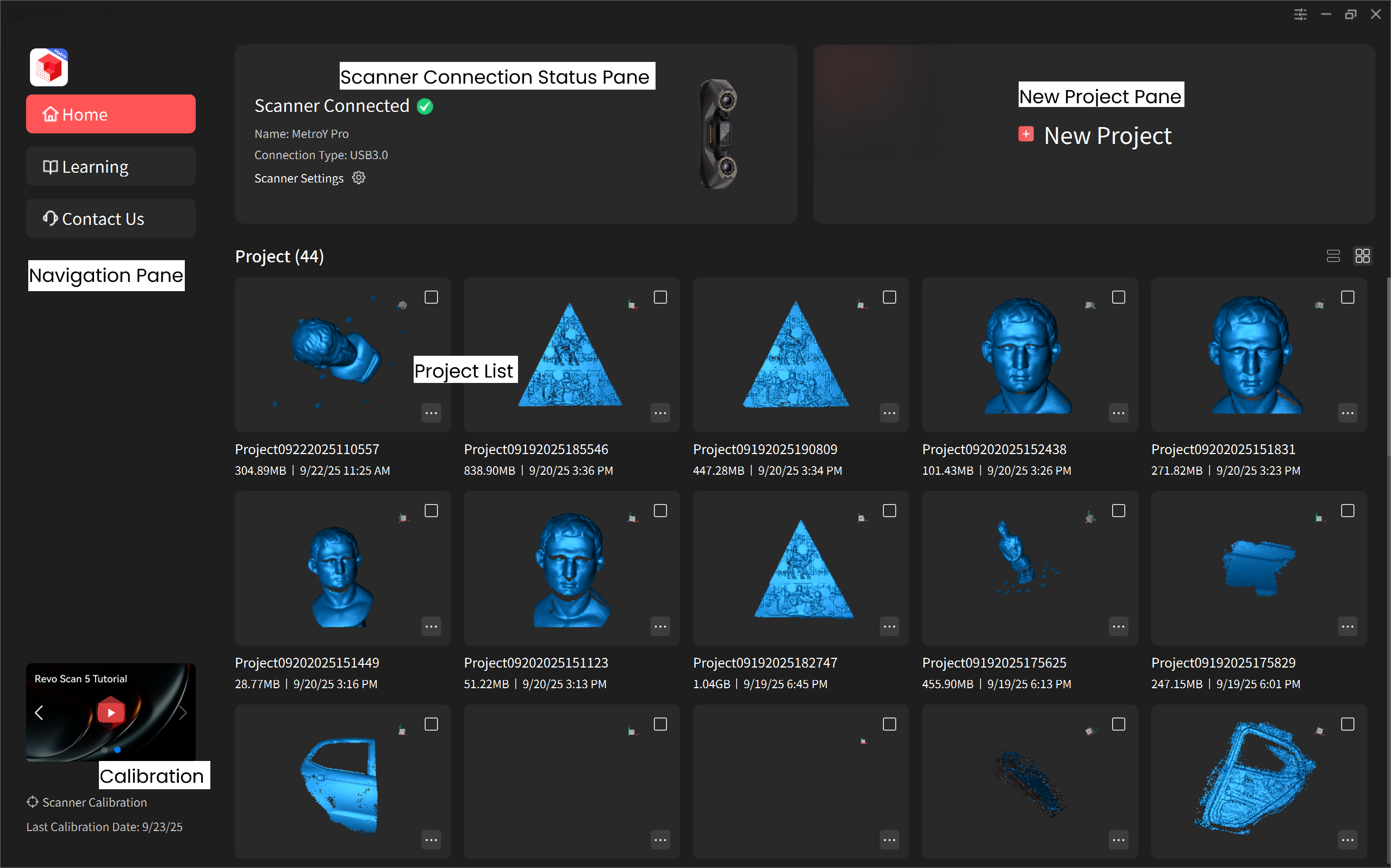
¶ 3.2 Project Interface
Note: The software is subject to updates. Please refer to the actual interface of the latest software version.
¶ 3.3 Software Setting
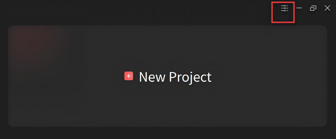
Click on the Settings icon " "in the top right corner, to access Revo Metro's settings.
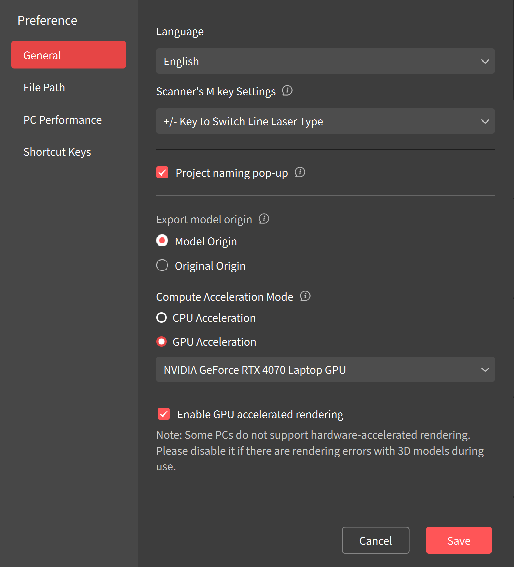
- Language: Select your preferred language.
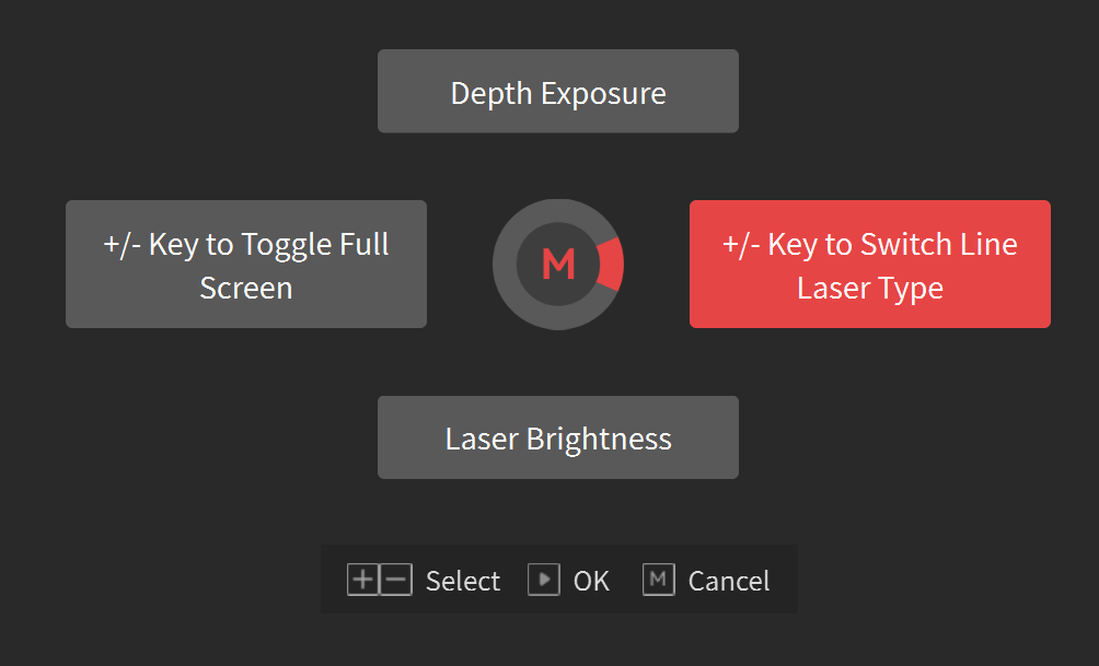
- Scanner's M key Settings:The Scanner's M key can switch between the following functions: Zoom in/Zoom out Central Preview Window/Switch between lase line modes/Adjust the Depth Camera exposure/Adjust the laser brightness. During a scan, short press the M key to quickly switch between those functions.
- Project naming pop-up: Untick the box to disable the project naming pop-up when creating a new project.
- Compute Acceleration Mode: Enhances frame rates stability and smoothness in the Cross Lines mode. It's recommended to use the suggested mode.
Note: GPU acceleration only supports NVIDIA GeForce RTX 30 Series and 40 Series GPUs on Windows.
- Enable GPU-accelerated rendering: Enable/disable GPU-accelerated rendering.
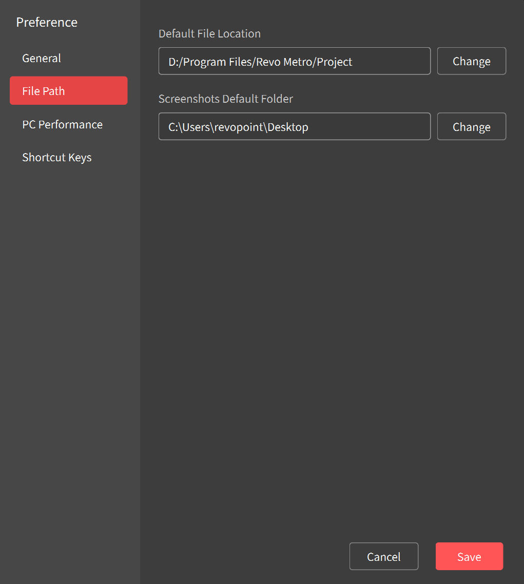
- Default File Location: Select the default file location to store projects and models.
- Screenshots Default Folder: Select the default file location to store screenshots.
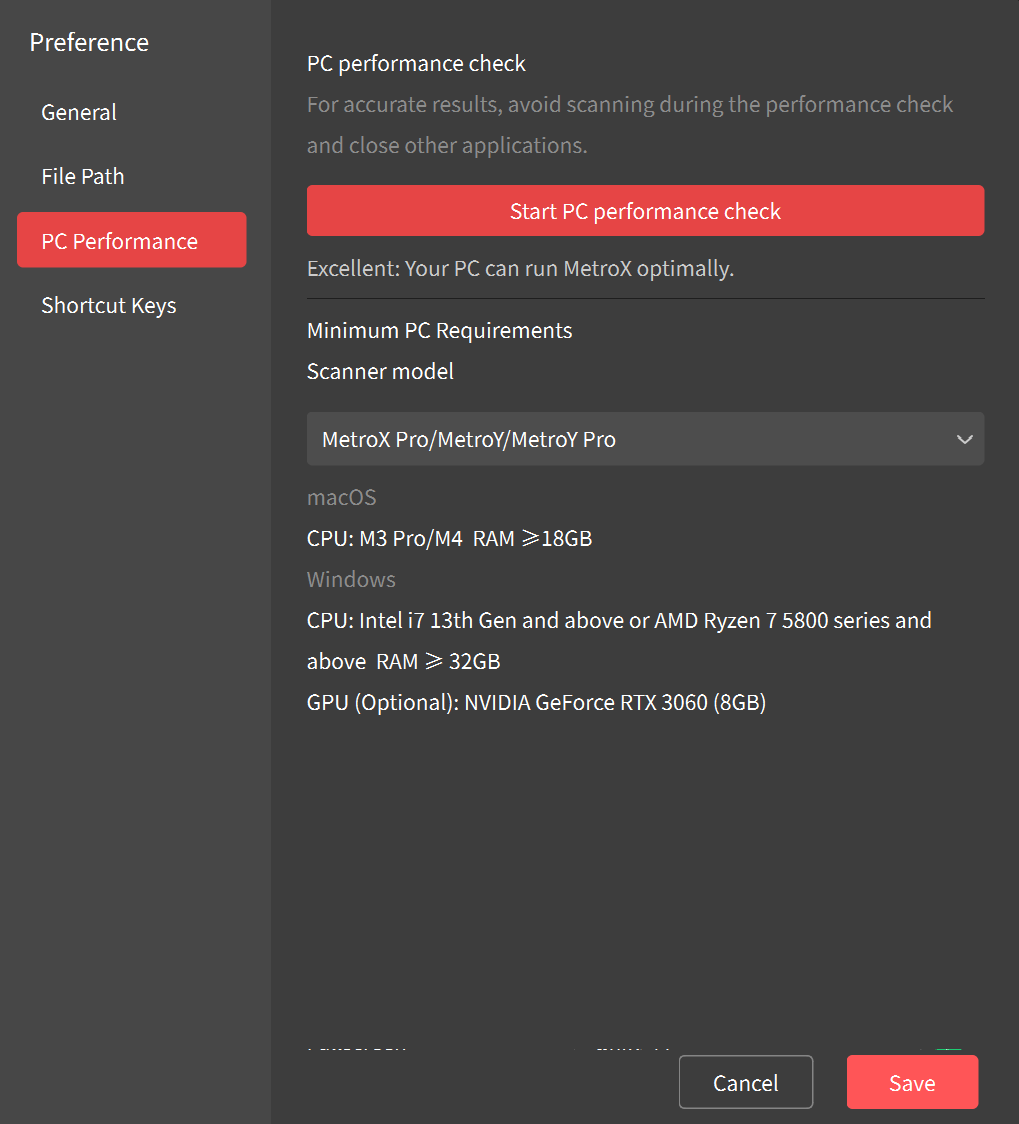
- Select your scanner model for PC's performance testing to determine if it can run Revo Metro smoothly.
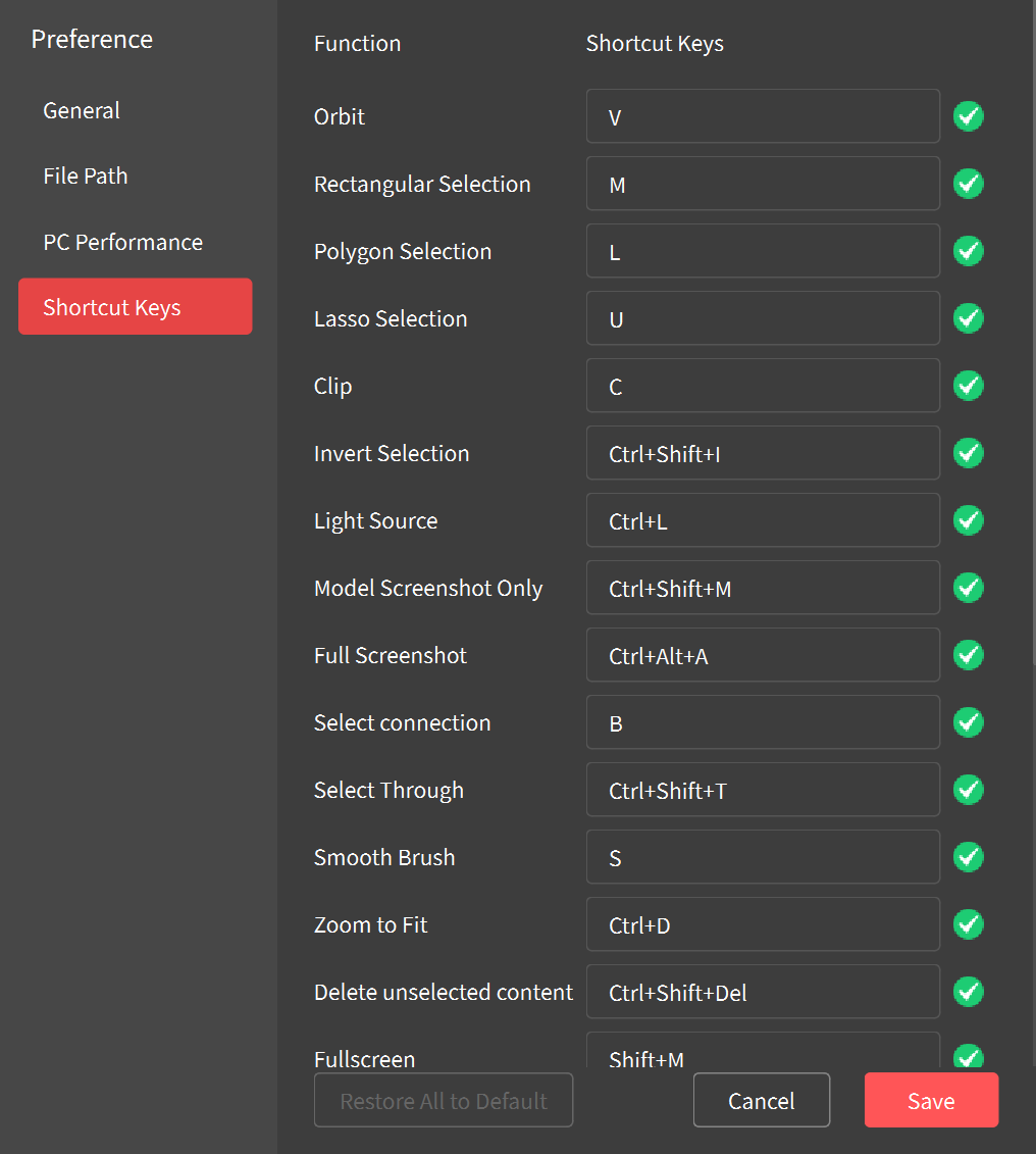
- Shortcut Keys: Displays the default shortcut key settings. You can change the settings as required.
¶ 4.Scanner Info & Wi-Fi Settings
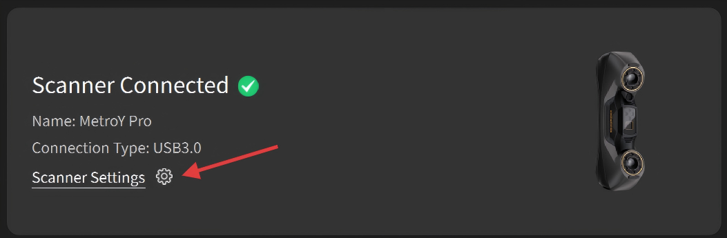
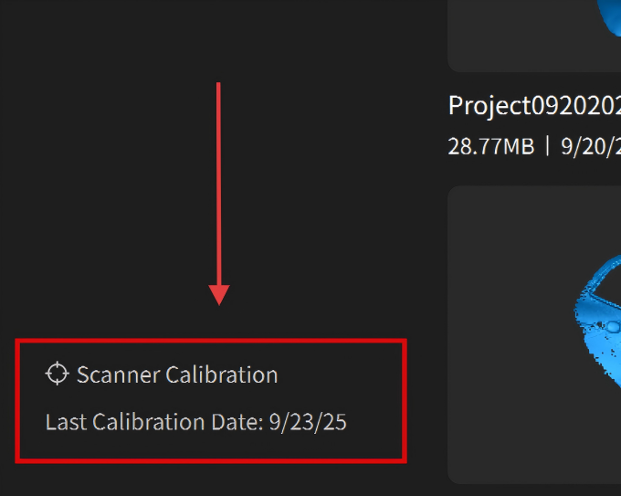
When a scanner is connected, click the settings icon on the Scanner Connection Status Pane to access the basic information of the currently connected scanner, including the device model, SN code, firmware version number, and the last calibration date.
¶ 4.1 Basic Deatils
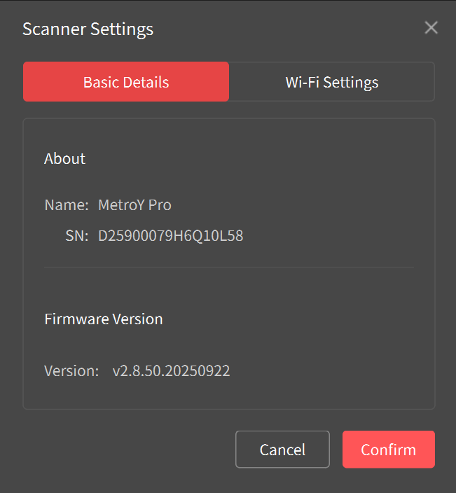
About: See the scanner's type and serial number.
Firmware Version: An “Update” button will be displayed when a new firmware version is available. Tap the button and follow the instructions to update.
¶ 4.2 Wi-Fi Settings
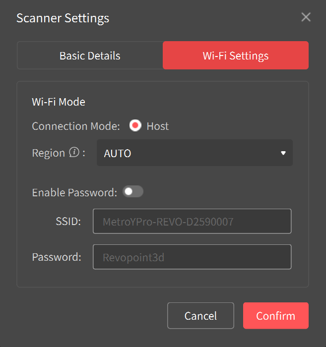
Connect a scanner to a PC via the scanner's Wi-Fi. The PC will lose internet access via Wi-Fi.
How to connect: Find the "Scanner Name-REVO X" Wi-Fi network and connect to it in your PC's Wi-Fi settings. Open Revo Metro, and the scanner should connect after a while.
Note:
1. You can change the scanner’s SSID name and set a password. If the scanner fails to connect over Wi-Fi, check that its region matches your country.
2. Remember to memorize the password if you enable it, or this will prevent you from using Wi-Fi.
¶ 5.Scanner Calibration
Before calibrating the scanner or scanning in laser line mode, it is necessary to warm up the device for 10 minutes to ensure optimal accuracy. Check the scanner's accuracy before each scan using the Scanner Calibration program on Revo Metro's Home page to ensure accuracy.
Steps:
① Click "Scanner Calibration" in the bottom left corner of the software and follow the prompts to proceed.
② Check the accuracy first.
③ If the accuracy check fails, calibrate the scanner according to the on-screen instructions if needed.
Note: To ensure the calibration results, connect your PC to a power supply before starting the calibration.
¶ 6.Software Functions
¶ 6.1 Scanning Controls
 : Click it to delete all captured data.
 /
/
 :
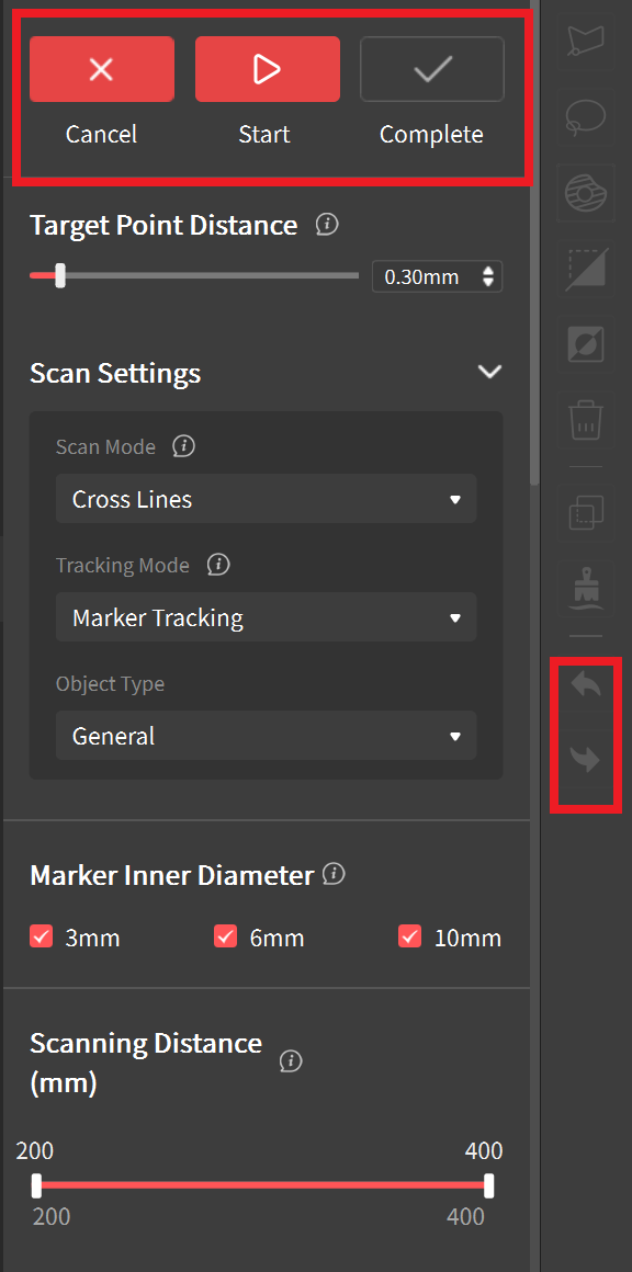
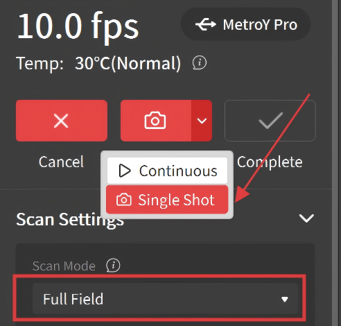
Click it to start or pause the scan. In Full Field mode (MetroX Series/MetroY Pro), click the drop-down tab on the Start/Pause button to switch between Continuous and Single Shot modes.
:
Click it to start or pause the scan. In Full Field mode (MetroX Series/MetroY Pro), click the drop-down tab on the Start/Pause button to switch between Continuous and Single Shot modes.
 : Click it when the scan is finished to move on to the editing process.
 /
/
 :
While paused scan in the Full Field mode or the Auto Turntable mode, the Redo and Undo buttons can remove or add back scan data. This can be done repeatedly.
:
While paused scan in the Full Field mode or the Auto Turntable mode, the Redo and Undo buttons can remove or add back scan data. This can be done repeatedly.
¶ 6.2 Scan Modes
Scanning modes differ by scanner model. Select the mode that best fits your specific needs.
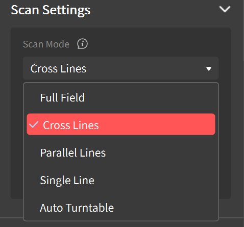
① Cross Lines: Designed for capturing shiny metals and black objects. It’s more efficient than Parallel Lines mode. (Requires markers for tracking.)
② Parallel Lines: Designed for capturing fine and complex details at a lower speed. (Requires markers for tracking.)
③ Single Line: Captures fine and complex details at a lower speed. (Requires markers for tracking.)
④ Full Field: Designed for efficiently capturing feature-rich objects in a short time.
⑤ Auto Turntable: The Turntable (Dual-axis Turntable or Large Turntable), scanner, and Revo Metro work together to automatically scan an object in single-shot mode, streamlining the process and generating a detailed, color-accurate 3D model if required.
¶ 6.3 Tracking Modes
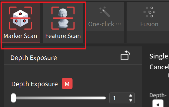
Before scanning, first select the Marker Scan or Feature Scan according to the object.
- Feature Scan: Aligns data by identifying the geometric features on the object's surface. For objects with distinct surface features and no repeating patterns.
- Marker Scan: Aligns data by identifying the spatial location of the markers placed on or around the object's surface. For capturing large flat surfaces that don't have distinct details. It must be used with marker points as tracking aids.
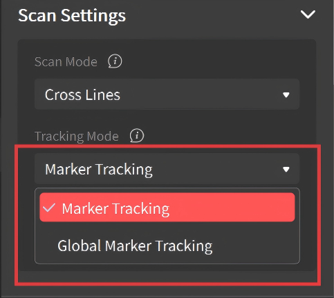
When using Marker Scan, the Tracking Mode can be set to either Marker Tracking or Global Marker Tracking.
* Global Marker Tracking can provide more accurate scanning results and smoother frame stitching. There are two steps: first, scan the markers to create global marker coordinates, and then scan the object based on these coordinates.
¶ 6.4 Target Point Distance
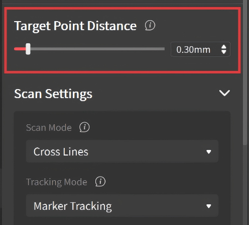
When using Cross Lines, Parallel Lines or Single Line modes, you can preset the target point distance, which is the space between adjacent point clouds during scanning. Setting a higher value will reduce scanning time.
Note: It is recommended to use the default target point distance value. The value setting will remain unchanged when switching between the laser line modes.
¶ 6.5 Scan Accuracy
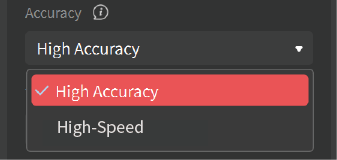
When using Cross Lines, Parallel Lines or Single Line modes, select appropriate accuracy.
High Accuracy: For capturing highly detailed objects.
High-Speed: For capturing larger objects quickly with faster frame rates and smooth frame stitching.
¶ 6.6 Object Type
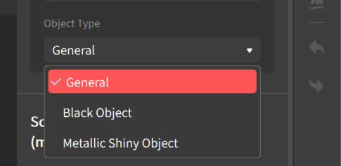
- General: This is the standard object type. Pick this type if the object doesn’t match the other options below.
- Black Object: Scan objects with dark surfaces, such as black or dark gray clothes. When using the Full Field or Auto Turntable scanning mode, some shiny dark items which will absorb or reflect light may still need to be treated with scanning spray to make them scannable.
- Metallic Shiny Object: Scan objects with metallic surfaces that reflect light, such as aluminum, steel, copper, and other types of metal.
Note: Available object types depend on the selected scan modes. INSPIRE 2 can also select Outdoor Object for scanning.
¶ 6.7 Marker Inner Diameter
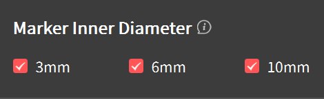
Select the inner diameter of the markers currently in use to enhance scanning accuracy.
Note: Only Revopoint standard marker sizes are supported.
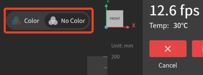
¶ 6.8 Color Scanning
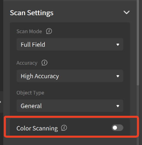
Enable it to capture color data when using Auto Turntable mode(MetroX Series/MetroY Pro/MetroY Ultra)and Full Field mode(INSPIRE 2). When performing a color scan, ensure the object is evenly lit with soft light for optimal color capture results. When a color scan is performed, you can toggle between displaying or hiding the model’s color.
¶ 6.9 Base Removal
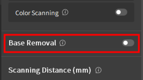
Toggle it on to enable automatic deletion of any unwanted flat surfaces detected (e.g., a table or floor) when using Full Field or Auto Turntable mode. If scanning an object with many flat surfaces, turn this off to avoid deleting any of the object’s surfaces.
¶ 6.10 Scanning Distance
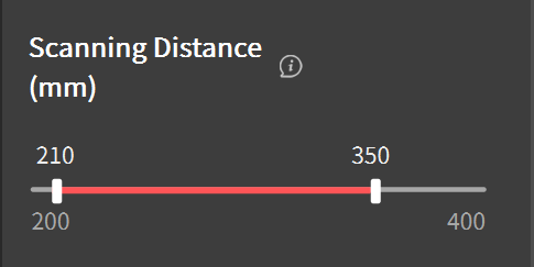
Use the slider to adjust the Depth Cameras' working distance to filter out unwanted background or foreground objects. Both a minimum and maximum distance can be set.
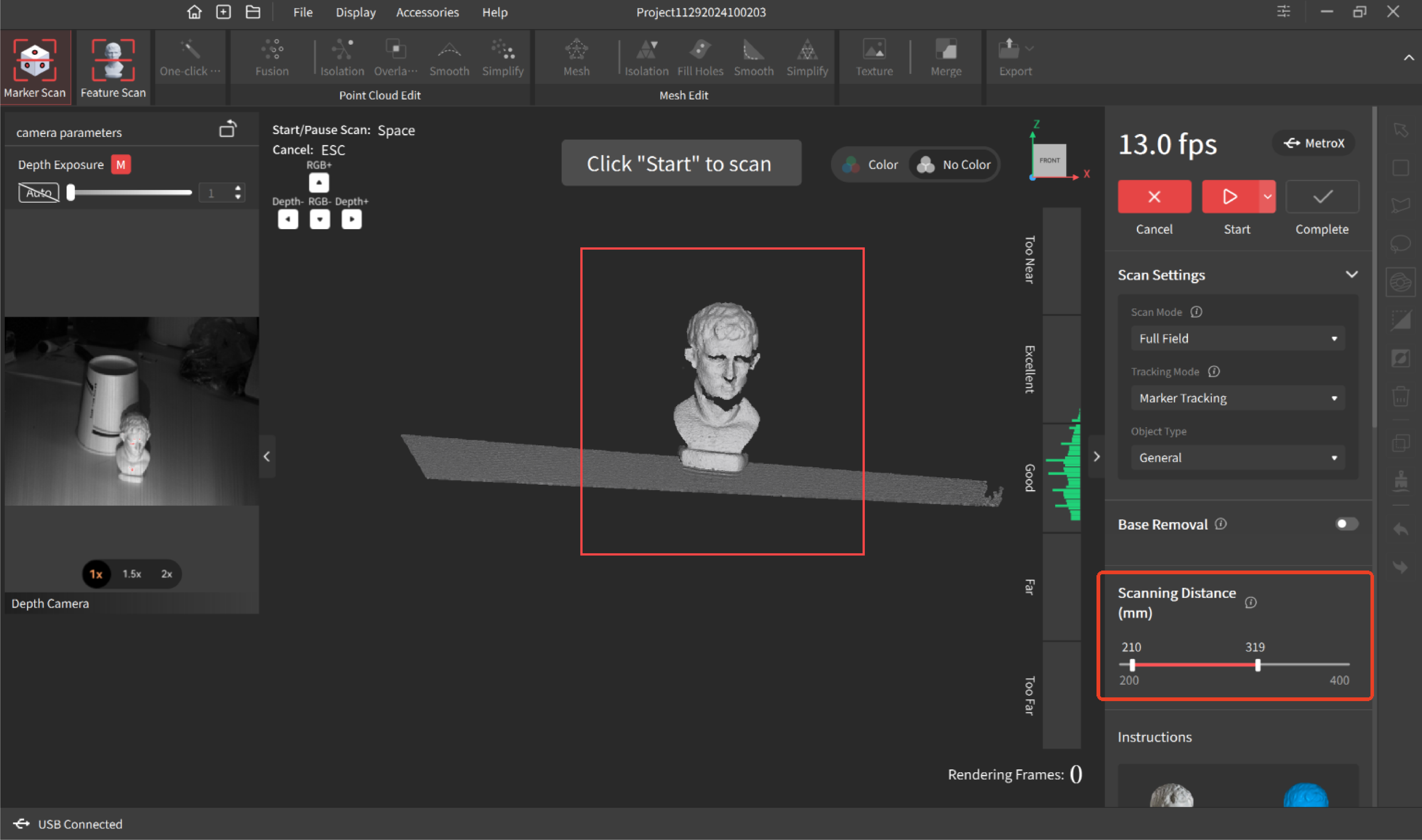
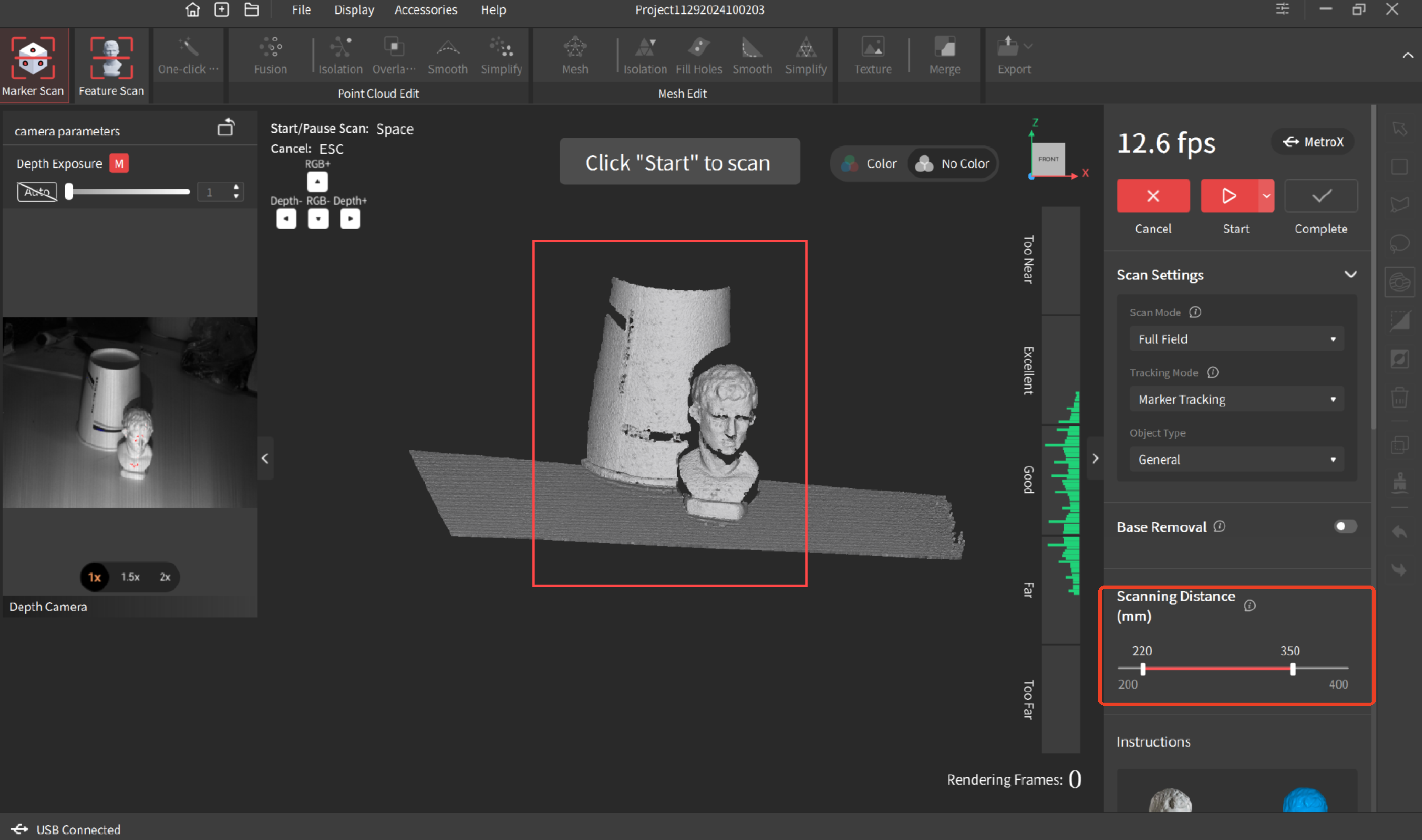
Note: Within the same project, if the distance is set for the first scan, it will be automatically saved for subsequent scans.
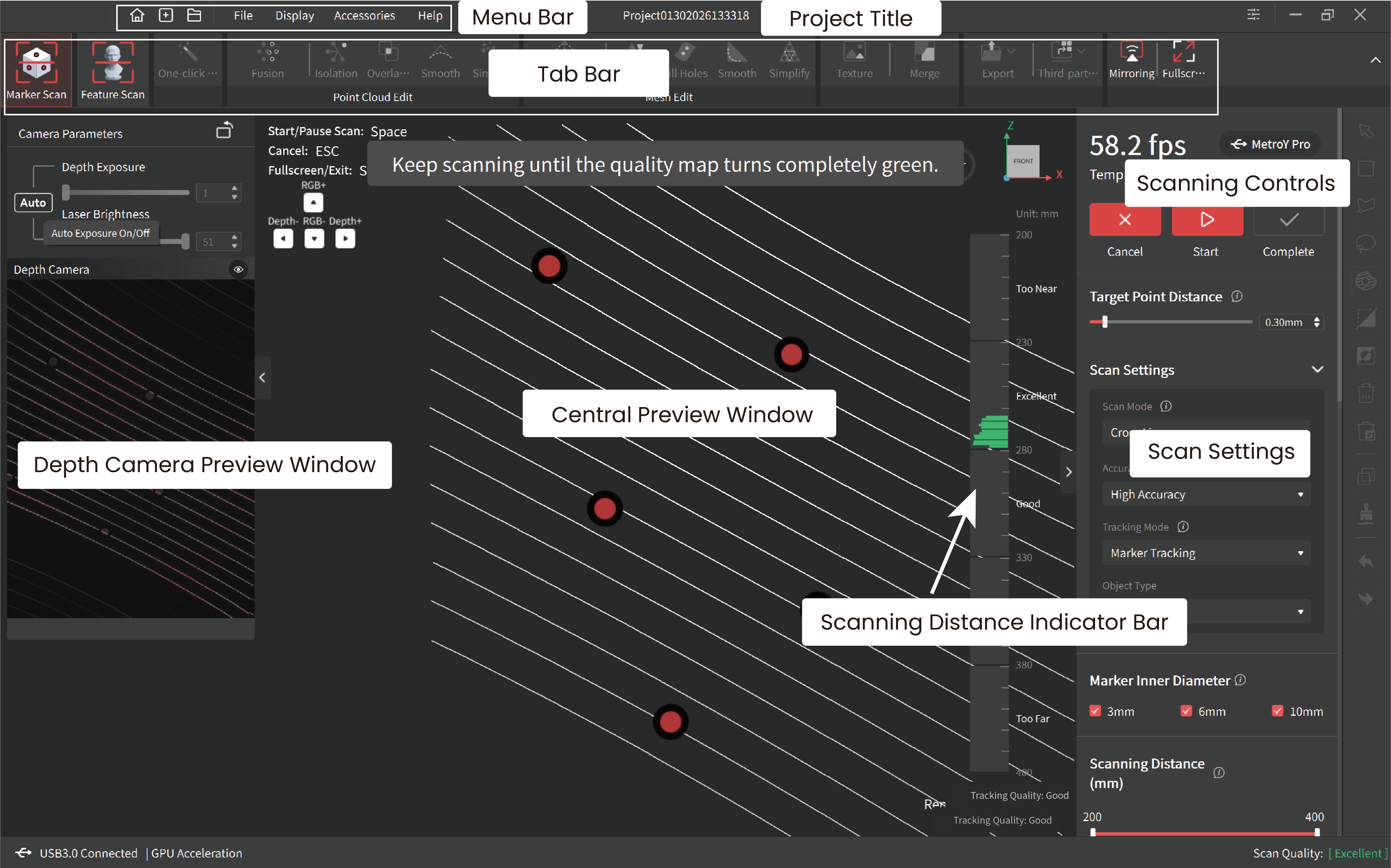
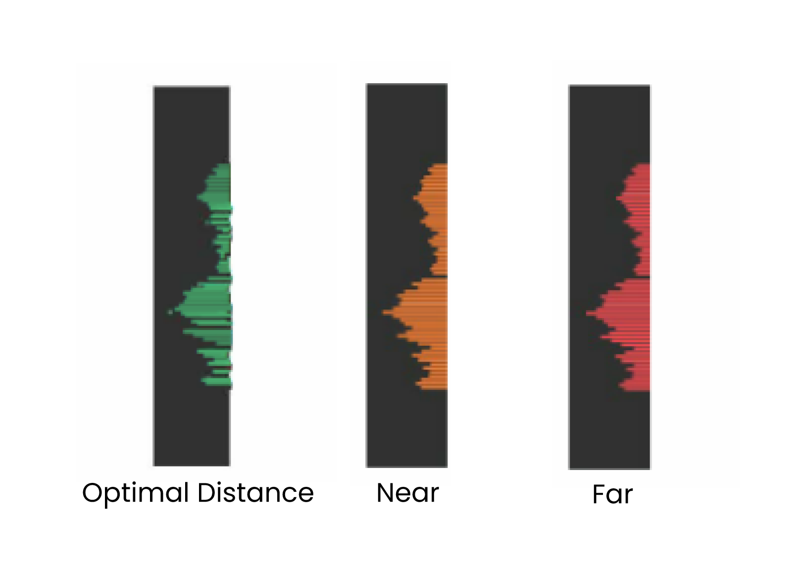
¶ 6.11 Scanning Distance Indicator Bar
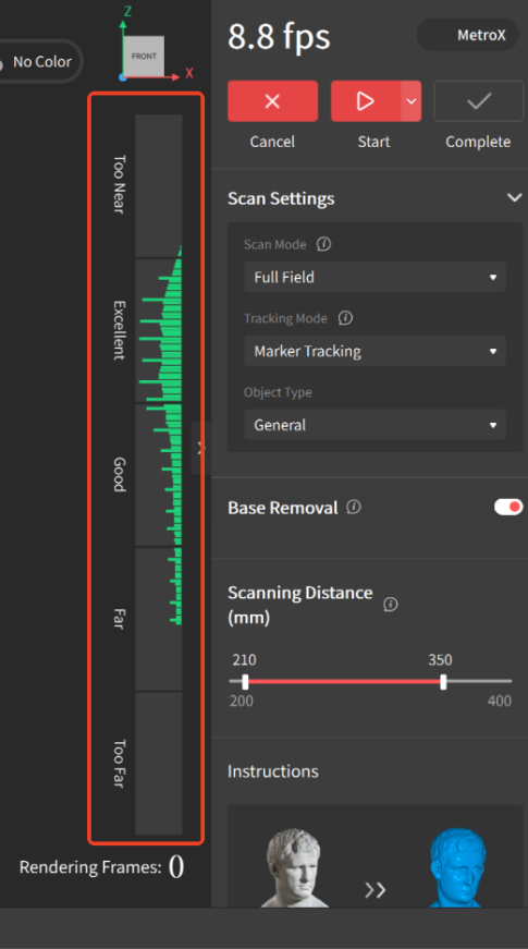
Adjust the scanning distance before a new scan. The distance indicator bar shows the distance between the object and the scanner. It's suggested to maintain the indicator within the optimal (green) range.
¶ 6.12 Camera Settings
(1)Depth Camera
Adjusting the cameras' parameters before starting a scan is crucial to getting a good 3D model.
Note: When the scanning starts, the camera preview window will be automatically hidden. You can manually click the  button in the upper-right corner of the preview window to make it displayed.
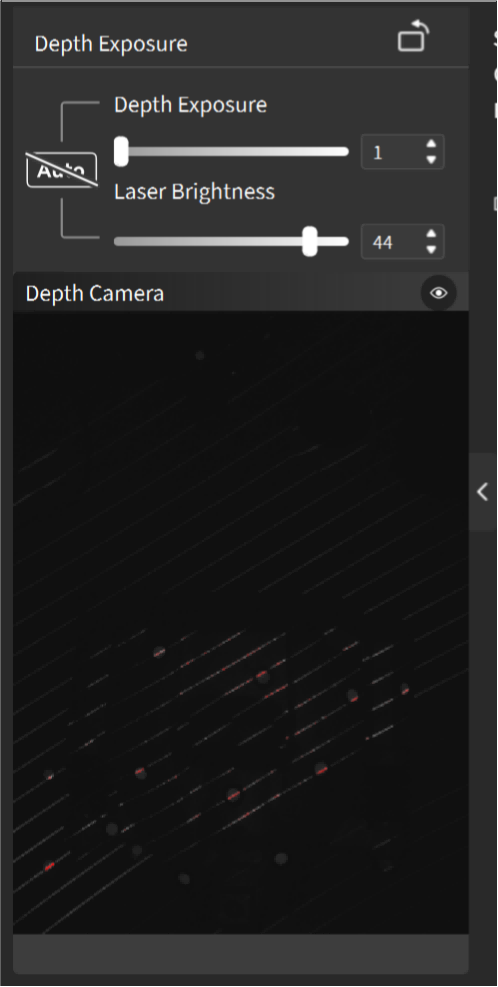
The exposure of the depth camera can be set to automatic exposure or manually adjusted. It's recommended to use the default values.
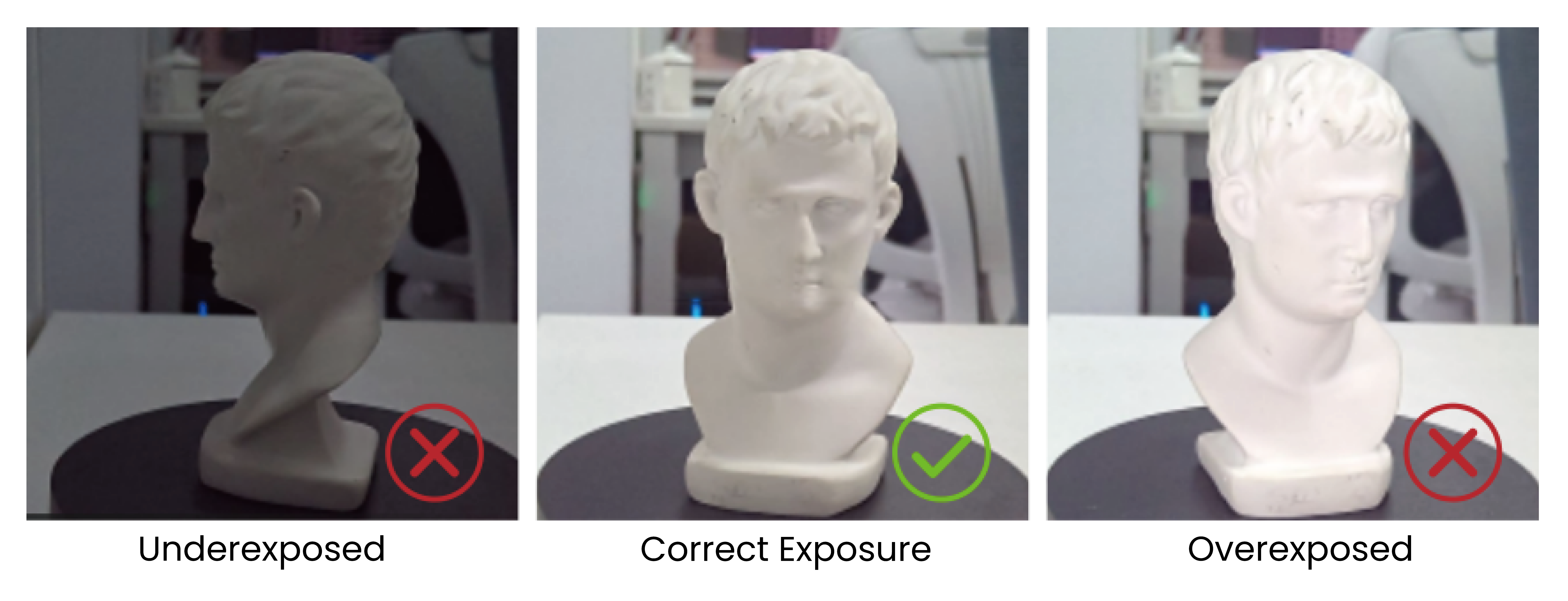
When manually adjusting the exposure in laser scanning modes, ensure that the object color in the depth camera preview window is gray.
When manually adjusting the exposure in Full Field mode or Auto Turntable mode, ensure the red or blue parts are as less as possible in the depth camera preview window.
It's recommended that you use the default value to avoid affecting the scan's effect.
(2)RGB Camera
To capture an object’s color accurately during a scan, please ensure it is evenly lit with soft light, and the RGB camera’s exposure and white balance have been adjusted.
222.jpg)
- Adjusting Exposure
Click the Auto button to turn on automatic exposure, or click it again to turn off automatic exposure and use the slider to manually adjust the exposure setting.
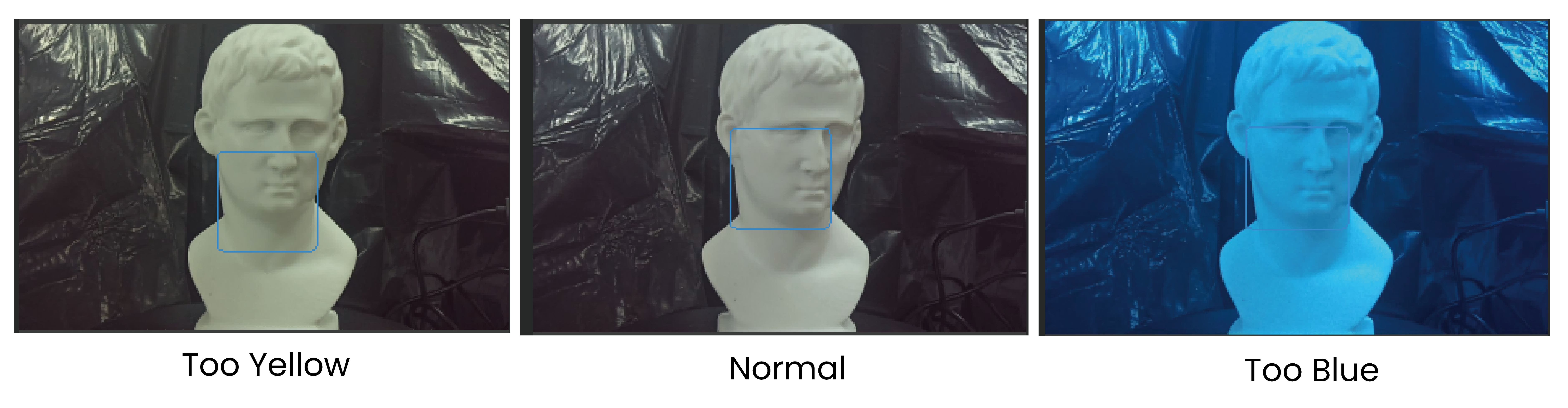
- White Balance
Click the Auto button to turn on automatic white balance, or turn off automatic white balance and use the slider to manually adjust the white balance until the colors look true to the actual object, ensuring they are neither too warm nor too cool.
¶ 6.13 Scan Quality
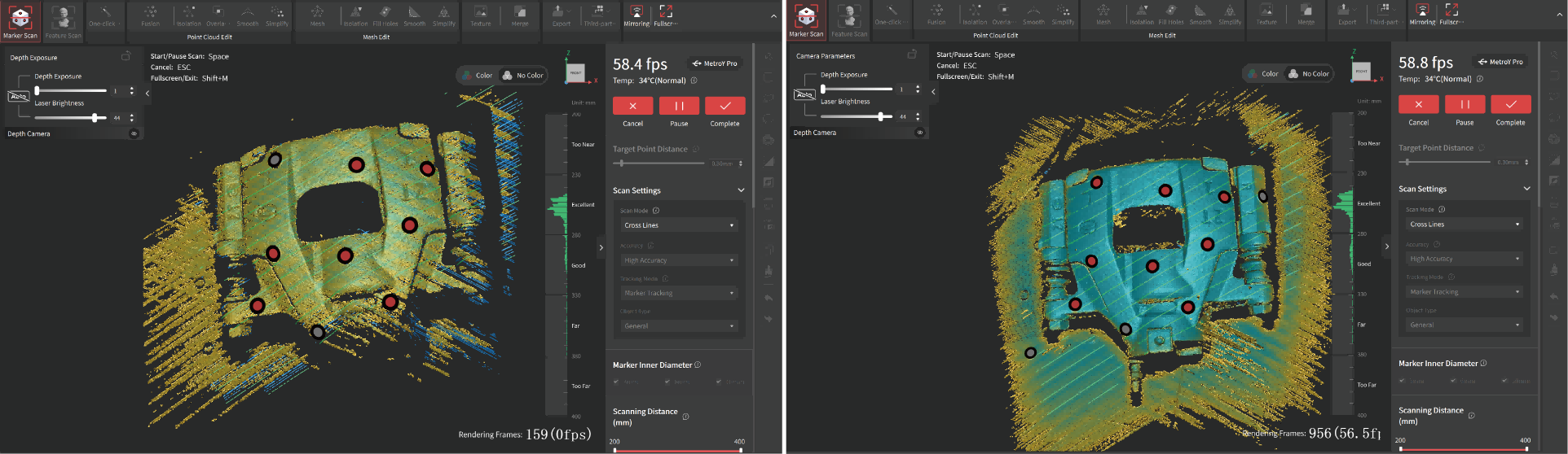
When scanning with laser line modes (Cross Lines, Parallel Lines and Single Line), the point clouds turn blue as more data is captured. Blue indicates higher quality, so it's best to scan the same areas from different angles and finish when the model is totally blue.
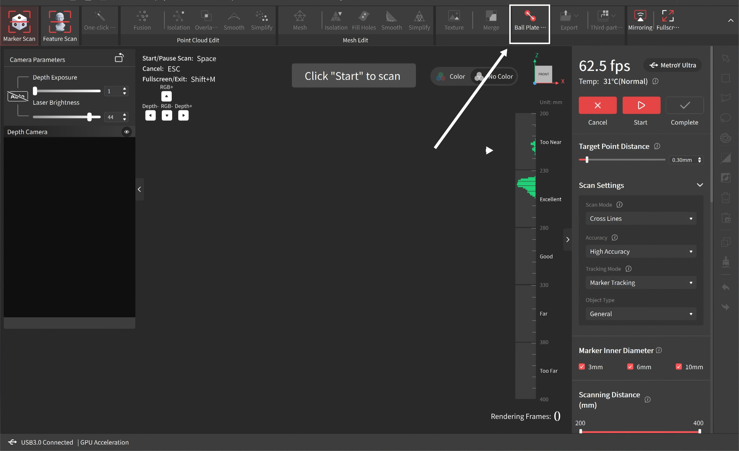
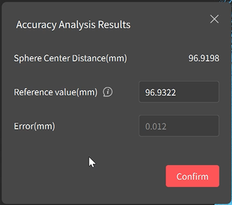
¶ 6.14 Ball Plate Measurement
The Ball Plate Measurement function captures the center distance between spheres by scanning a dedicated calibrated Ball Plate and compares it with its certified reference value, enabling fast and reliable on-site accuracy verification.
Take the cross-line scanning mode as an example to illustrate the steps:
① Click “New Project” to enter the scanning interface, then select “Ball Plate Measurement” at the top to start the workflow.
② Read the measurement instructions and then click “Got it.”
③ Follow the on-screen guidance to perform a global marker scan of the Ball Plate until all markers are fully captured.
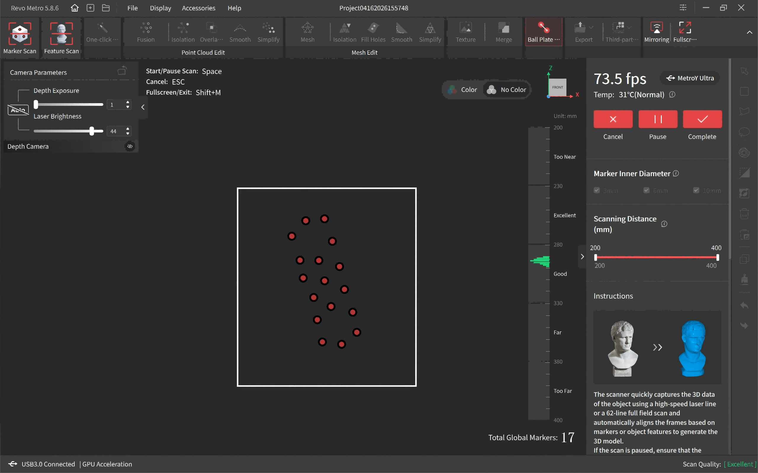
Note: You can check the progress via the “Total Global Markers” indication in the lower right corner.
④ After completing marker acquisition, click “Point Cloud Scan” and select cross-line scanning mode. Move the scanner steadily and scan the Ball Plate from multiple angles to capture the spheres as completely as possible.
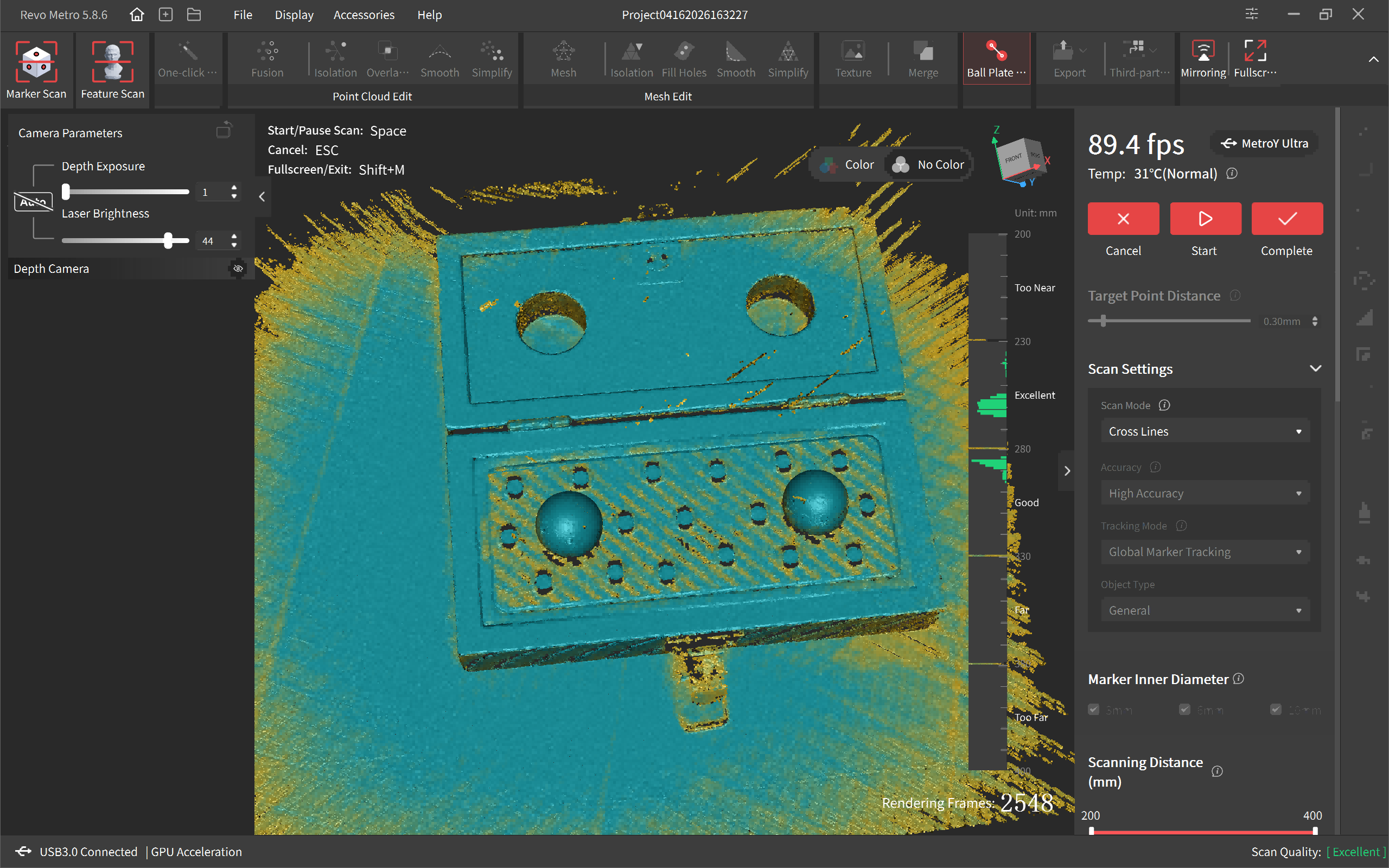
⑤ Click “Finish” after completing the scan. The system will automatically perform data fusion and generate an accuracy analysis report. Enter the Ball Plate’s reference value (certified value) to obtain deviation results. The certified reference value can be obtained by scanning the QR code or by checking the label on the Ball Plate.
Note: It is recommended to perform calibration and Ball Plate measurement to acquire the best accuracy before your first scan.
🔺Precautions:
• To ensure accuracy, it is recommended to keep the difference between the scanner temperature and the calibration temperature within ±2°C before performing Ball Plate measurement.
• The Ball Plate is a precision instrument. Handle and store it properly. Do not touch the spheres or markers with your hands or other objects to avoid scratches or contamination.
• After using, ensure the case latch is securely locked.
• Do not drop the Ball Plate during use, as this may compromise its accuracy.
¶ 6.15 Mirroring/Fullscreen
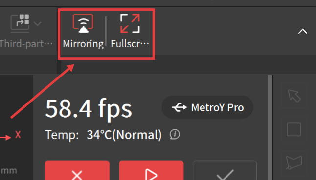
Mirroring: Supports mirroring the computer screen to a mobile device via Revo Mirror, enabling real-time preview and control of the scanning process. For detailed operations, refer to the Revo Mirror User Manual.
Fullscreen: Click the Full Screen button to enter full-screen preview. Reclick or use the shortcut Shift + M to exit full-screen display.
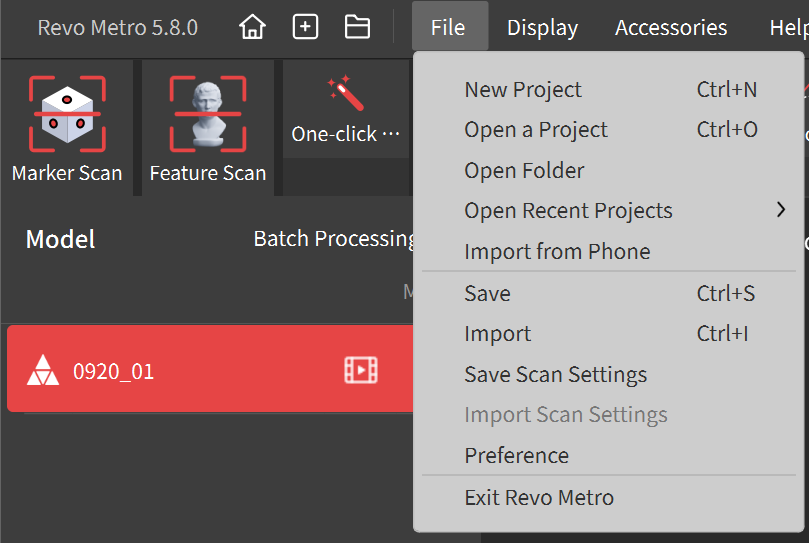
¶ 6.16 Saving/Importing Scanning Settings
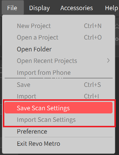
Set the scan's settings > In the Menu Bar, click File > Save Scan Settings, name the setting, and choose a location to save it. Or click Import Scan Settings, select the file containing the wanted setting, and click Open.
Note: Only the scanning settings for the currently connected scanner can be imported.
¶ 7.Scanning Steps
¶ 7.1 Cross Lines/Parallel Lines/Single Line
Before using laser line scan mode, you need to place markers on the objects. Click "Scanning Tips" to learn more tips about objects prerparation.
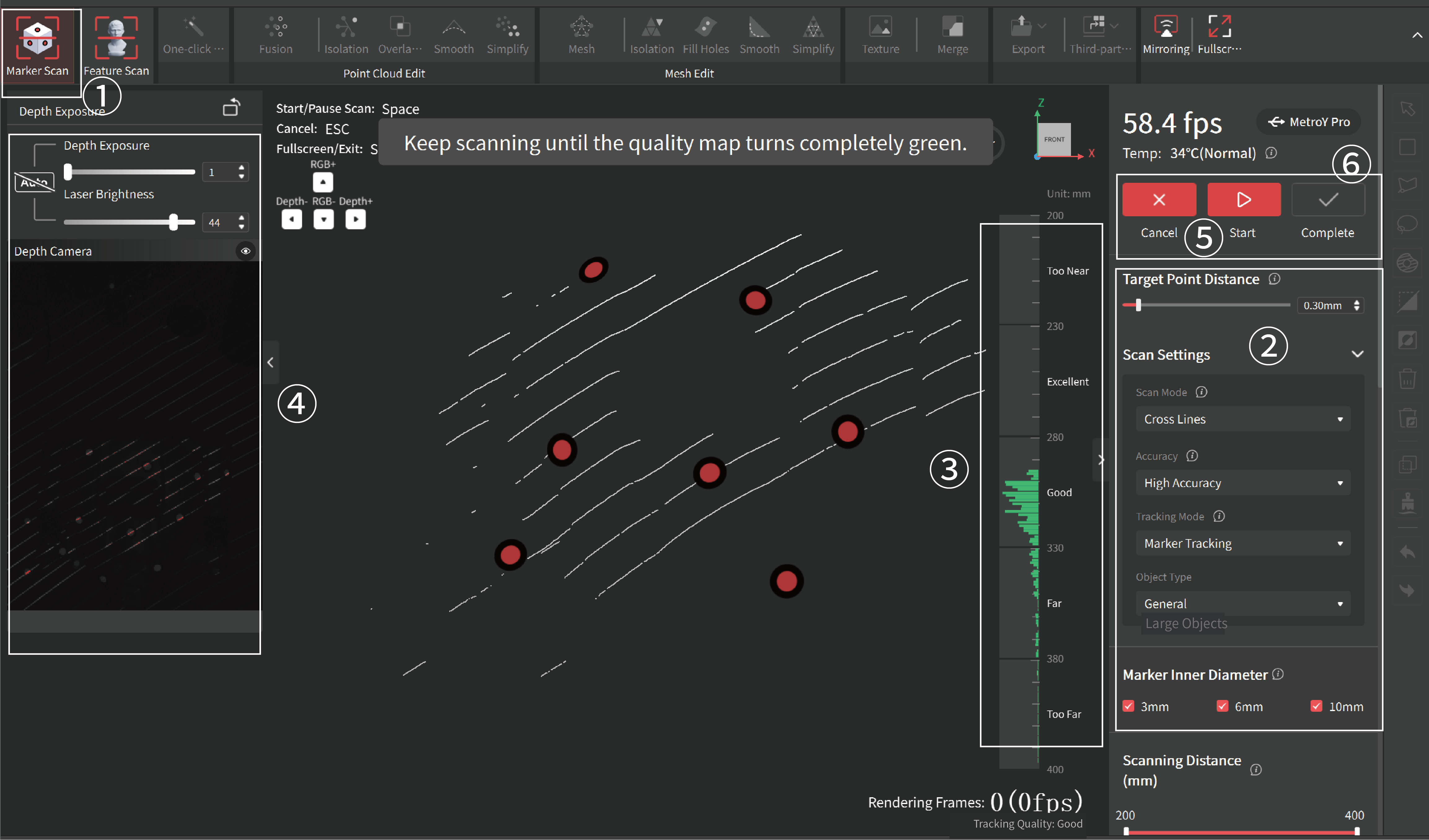
① Click the New Project to enter the project interface, and select Marker Scan.
② In Scan settings, select the scan mode (Cross-line mode / Parallel-line mode / Single-line mode), accuracy, and adjust the Target Point Distance as required.
③ Hold the scanner and adjust the distance between the scanner and the object until the scanning distance indicator bar shows Excellent or Good. Ensure at least 5 markers can be detected in a single frame during the scan.
④ Adjust the exposure by dragging the slider. It's recommended to use the default value and keep the whole object gray.
⑤ Click the  button on the back of the scanner or in the software to begin your scan. Move the scanner slowly and steadily around the object within the recommended distance. Click the button to pause and check your model anytime during your scan. If the model is incomplete, click the button to continue your scan.
⑥ Click the button to finish the scan when the model is complete.
Note: Please warm up the device for 10 minutes before using laser line scan mode for best accuracy.
¶ 7.2 Full Field
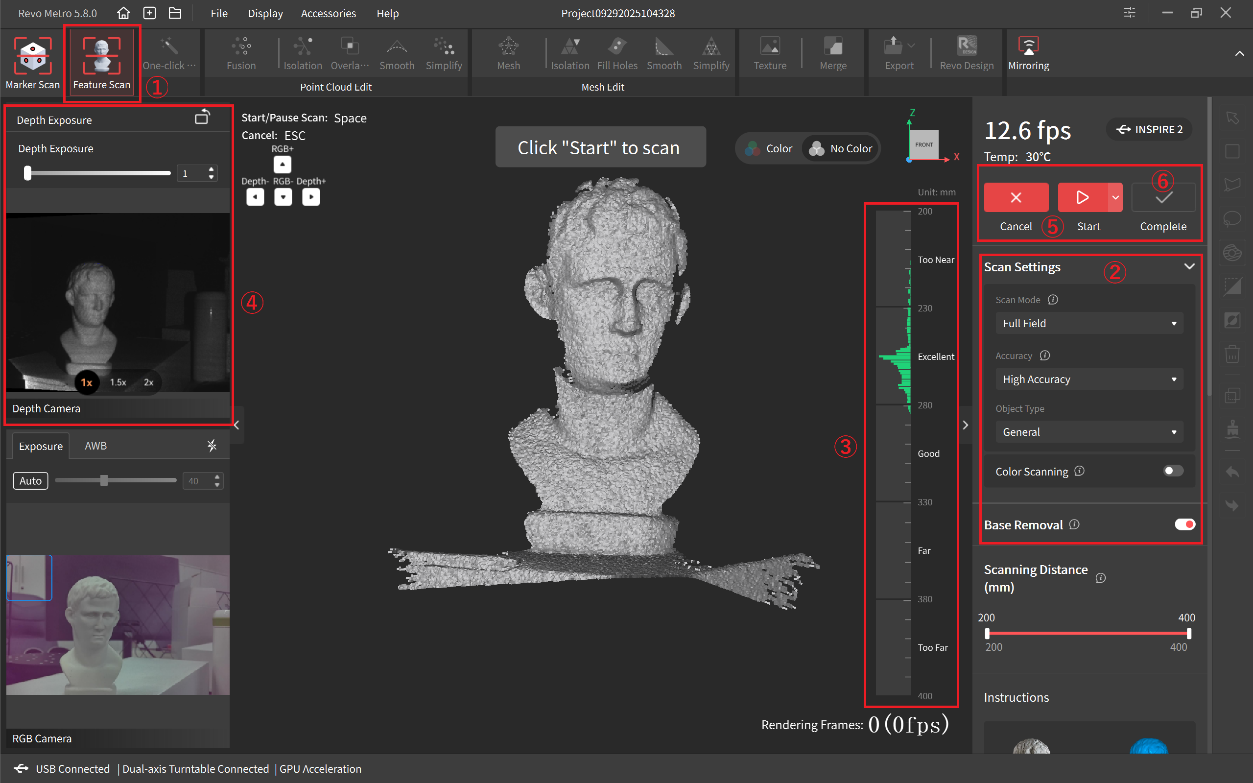
① Click the New Project button on the Home page to enter the project interface. Select Marker Scan or Feature Scan according to your requirements.
② In Scan Settings, choose Full Field mode and Object Type.
③ Move the scanner closer or further away from the object until the scanning distance indicator bar shows Excellent or Good.
④ Click the Auto button to automatically set the Depth Cameras' exposure, or turn off the Auto exposure and adjust it by dragging the slider until there are as few blue and red areas on the object in the Depth Camera preview window as possible and the whole object shows gray.
⑤ Click the button on the back of the scanner or in the software to begin your scan. Move the scanner slowly and steadily around the object within the recommended distance. Click the button to pause and check your model anytime during your scan. If the model is incomplete, click the button to continue your scan.
⑥ Click the button to finish the scan when the model is complete.
¶ 7.3 Auto Turntable (MetroX Series/MetroY Pro/MetroY Ultra)
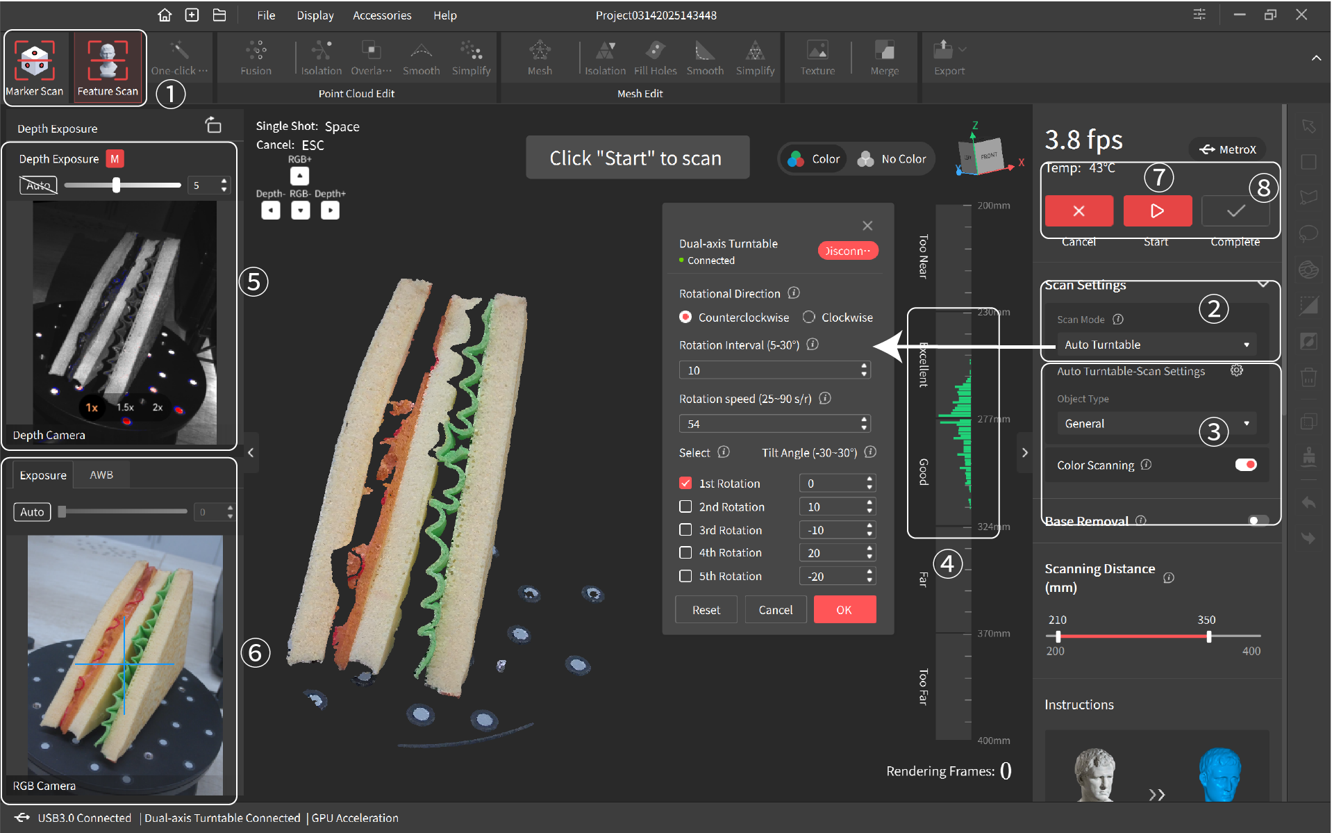
① Click the New Project button on the Home page to enter the project interface. Select Marker Scan or Feature Scan according to your requirements.
② In Scan Settings, choose Auto Turntable mode. Click the Settings button to connect the turntable and set the rotation direction, rotation interval, and rotation numbers. Beginners can use the default settings.
③ Choose the Object Type according to your requirements. If required, toggle Color Scanning and ensure the object is evenly lit during scanning.
④ Move the scanner closer or further away from the object until the scanning distance indicator bar shows Excellent or Good.
⑤ Click the Auto button to automatically set the Depth Cameras' exposure, or turn off the Auto exposure and adjust it by dragging the slider until there are as few blue and red areas on the object in the Depth Camera preview window as possible and the whole object shows gray.
⑥ You also must adjust the RGB Camera's exposure when doing a color scan. Click the Auto button to automatically set the exposure, or turn off the Auto exposure and adjust it by dragging the slider until the object's color in the RGB preview window is clear and sharp.
⑦ Click the button, and the software will control the turntable to automatically finish the scan with single shot mode according to your settings. If the model is incomplete, click the button to continue your scan after resetting the scan path.
⑧ Click the button to finish the scan when the model is complete.
¶ 8.Model Editing
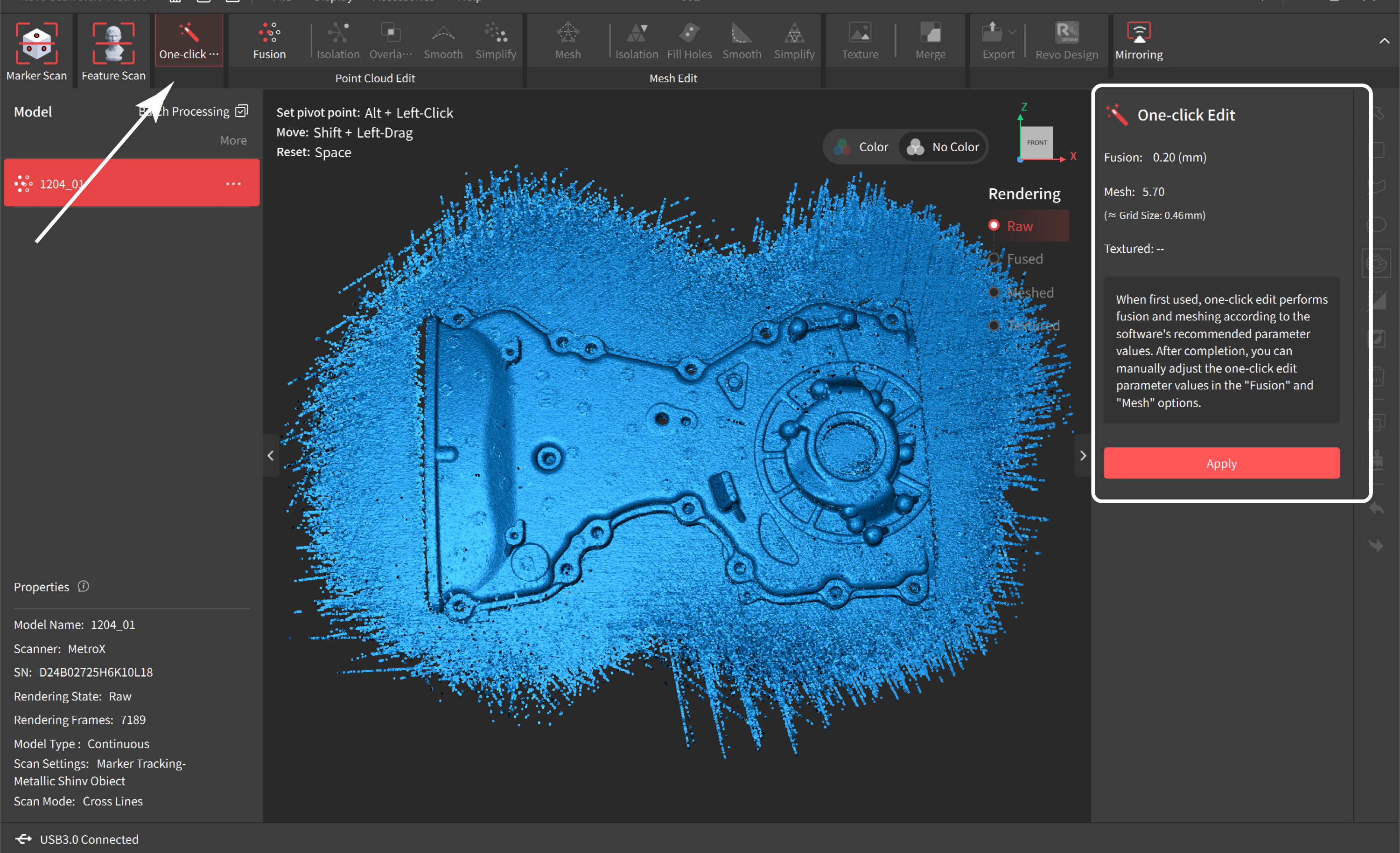
¶ 8.1 One-click Edit
Revo Metro has a powerful one-click processing feature that automatically performs fusion, meshing, and texturing (if a color scan was done) based on automatically detected optimal settings for the point cloud. Tap the "Apply" button to perform the "One-Click Edit" function. Click the "Cancel" button to cancel the process.
¶ 8.2 Point Cloud Editing
¶ 8.2.1 Point Cloud Fusion
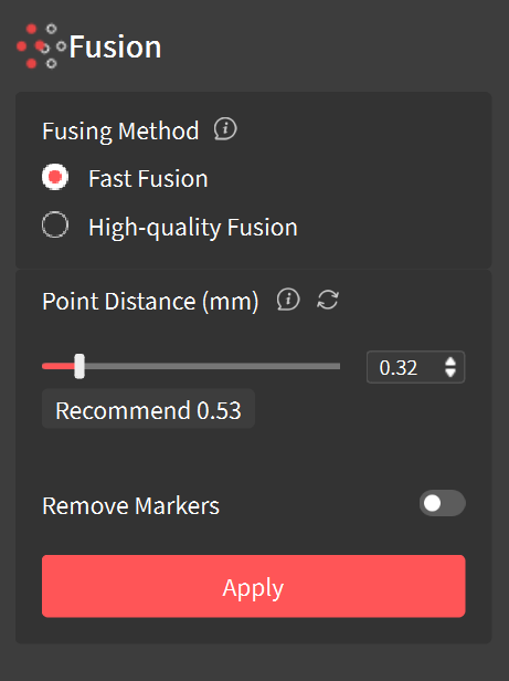
Fusion is fusing the raw scan data captured by the scanner into a unified point cloud model.
Fast Fusion:Fast fusion is suitable for quick previews of point cloud processing results, offering shorter processing times but with increased noise.
High-quality Fusion:High-quality fusion uses a refined fitting method to generate a high-quality point cloud, but it requires more computational time.
Note: Supported point cloud fusion methods vary by scan mode. Please refer to the actual software interface to perform point cloud fusion.
• Point Distance: The average distance between the adjacent points in a fused model. The software will suggest an optimal point distance for each scan, but different values can be specified depending on your requirements.
Note: Set a lower point distance for objects that have a lot of detail. Set a higher point distance for objects with many flat featureless surfaces.
• Remove Marker: Enable it to automatically remove the point cloud data caused by the marker points placed on or around the object. A higher hole radius value will result in larger holes being left after the cleanup.
Tap the "Apply" button to perform the "Fusion" function, and click the "Cancel" button to cancel it.
¶ 8.2.2 Point Cloud Isolation
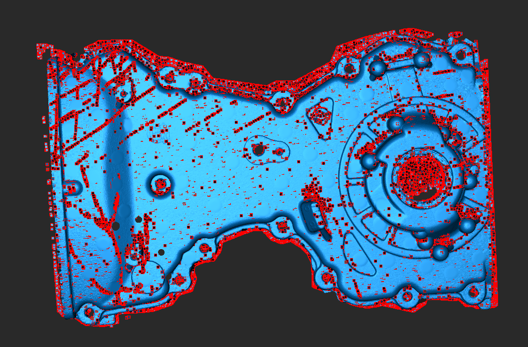
Detects and removes the isolated point cloud data disconnected from the main point cloud model (see the red area in the figure).
Isolation Rate: The percentage of points within isolated point clouds relative to the total number of points. Setting a higher rate will detect more isolated point clouds.
¶ 8.2.3 Point Cloud Overlap Detection
Identifies and deletes overlapping data in the point cloud for a more consistent model. It can be used repeatedly to simplify point cloud data.
Vertical Distance: The distance between the overlapped point cloud noise and the captured surface area. If it's less than the set value, it's considered noise and removed. If it exceeds the set value, it's not removed.
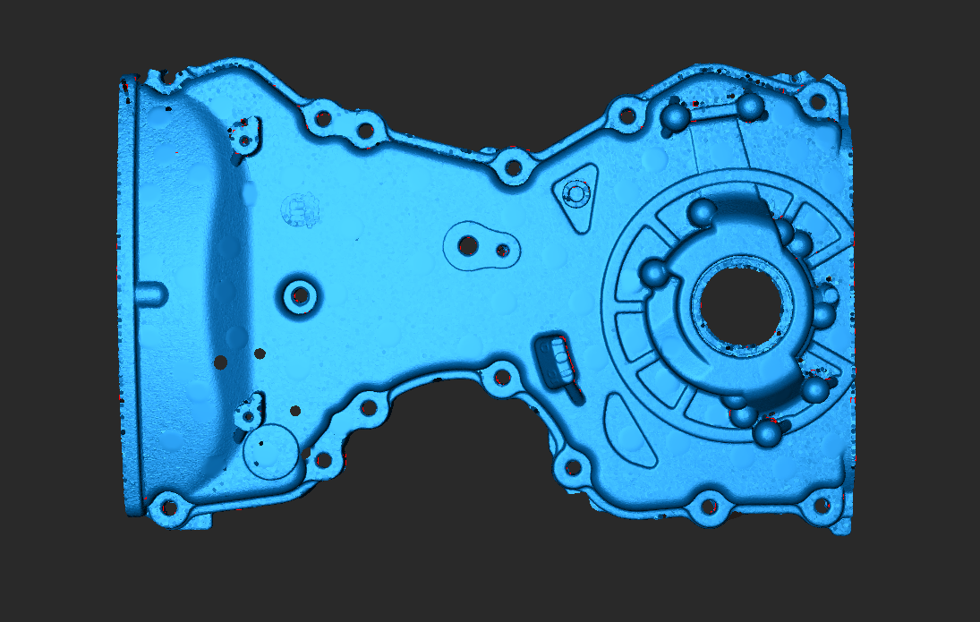
¶ 8.2.4 Point Cloud Smoothing
Removes noise from the point cloud to make it smoother.
To use it, select its strength and the number of times it applies smoothing consecutively.
Note: For feature-rich models, excessive smoothing may result in loss of details (see the figure below).
¶ 8.2.5 Point Cloud Simplify
Reduces the density of the point cloud and the amount of data for more manageable processing, storage, and sharing. There are two different downsampling methods:
• Uniform: Removes the set percentage of points across the model evenly.
• Geometric: Intelligently identifies flat or plain surfaces in the point cloud and will remove the set percentage of points from these areas while leaving more complex areas alone to maintain the details.
Ratio: The percentage of simplified point cloud data to the total amount of data. Setting a higher ratio will delete more point cloud data from the model.
Note: Selecting a too large ratio may impact the model's quality.
¶ 8.3 Mesh Editing
¶ 8.3.1 Meshing
A mesh is created by constructing triangles from the points in the point cloud to create a solid surface. The point cloud must be meshed before being used in most 3D modeling or slicing software.
Fast Meshing:It performs triangulation on point cloud data to quickly generate a mesh model. Mesh generation is required before performing operations like hole filling and smoothing. Ideal for scenarios where a quick preview of the mesh is needed.
High-quality Meshing:It performs triangulation on point cloud data using custom quality settings to generate a mesh model.
• Quality: The mesh model's density and level of detail. Setting a higher value results in a denser and more detailed mesh model but spends more time.
• Hole Filling (Auto): Revo Metro automatically identifies and fills all the holes on the mesh model.
• Ratio: The percentage of the hole diameter to the overall mesh size. The holes smaller than this ratio will be filled.
Note: The Hole Filling (Auto) function is for small holes. Use the Fill Holes tool in the mesh editing tab to fill larger holes.
Tap the "Apply" button to perform the "Mesh" function.
¶ 8.3.2 Mesh Isolation
Detects and removes the isolated mesh data disconnected from the main mesh.
Isolation Rate: The percentage of an isolated mesh relative to the total number of meshes. Setting a higher value will detect more isolated mesh data.
¶ 8.3.3 Mesh Smoothing
Removes noise from the mesh model to make it smoother.
To use it, select its strength and the number of times it applies smoothing consecutively.
¶ 8.3.4 Mesh Simplify
Reduces the mesh data in the model for more manageable processing, storage, and sharing.
Ratio: The percentage of simplified mesh data to the total data volume. Setting a higher ratio will remove more details, resulting in a smaller file size.
¶ 8.3.5 Fill Holes
Detects all holes on the model's surface. Select the holes and fill them with a Plane or Curved surface.
¶ 8.4 Texturing
The Texture function is only available after a color scan in Auto Turntable mode (MetroX Series/MetroY Pro/MetroY Ultra) and Full Field mode (INSPIRE 2). Please perform point cloud fusion before applying the texture.
Texture is applying the color data captured by the RGB camera to the mesh to create a high-quality colored 3D model. There are two texturing methods:
Color Image:
This method maps the image data captured by the scanner's RGB Camera on the mesh's surface to create a colored model.
Vertex Coloring:
This method generates textures from the mesh's vertices color. Click the "Apply" button to perform the "Texture" function and click the "Cancel" button to cancel the process.
¶ 8.5 Model Merging
The merging function supports the alignment of multiple scans in a project into a new model. Please note that the scans can only be merged after they are fused. There are two alignment methods: Feature Alignment and Manual Alignment.
¶ 8.5.1 Manual Alignment
At least 3 reference points must be manually placed in matching locations on each model. Then, Revo Metro merges the two models by identifying and aligning the reference points. Only 2 models can be merged at a time.
• The number of corresponding reference points on both models must be the same.
• Avoid grouping the markers together in a small area.
• Zoom in on the features of each model to place the marker points carefully.
¶ 8.5.2 Feature Alignment
Select the models, and Revo Metro will automatically merge them by identifying and aligning the overlapping features in multiple models. The overlapping area between any two models should be more than 10% (for best results, 40% to 50% is recommended). Up to 9 fused models can be selected and merged simultaneously.
¶ 8.6 More Operations
Revo Metro supports one-click jump to third-party software such as Revo Design, Revo Measure or Geomagic Control X for further model processing and measurement.
Revo Measure: Revo Measure is a professional 3D metrology software designed for fast and accurate scan-to-CAD comparison and deviation analysis. It can be widely used in applications such as quality control, reverse engineering, and industrial design. Go to Revo Measure User Manual or Revo Measure Tutorial Video.
Revo Design: Revo Design is a compact and straightforward CAD software integrated with Revopoint scanning softwarre for seamless reverse engineering workflows. Click here to navigate to its user manual.
¶ 9.Tool Bar
The Toolbar provides multiple tools for manually selecting unwanted local data for detailed editing or deletion.
Note: The Tool Bar can't be used for raw data or textured models.
 |
Orbit Rotate the view in any direction. Clicking it will also de-select any previously selected areas. |
 |
Rectangular Selection Click and hold the left mouse button to draw a rectangle around any point on the model to select that area. |
 |
Polygon Selection Left-click to create anchor points to select a mesh's polygons (faces). The Polygon tool creates a straight line between each Anchor Point. Click on any edge of the area to be selected and release the mouse pointer to make an Anchor Point. |
 |
Lasso Selection Click and hold the left mouse button, then draw a shape around an area to select it. Release the mouse button, and the selection will be closed by connecting the current pointer location to the start location with a line. |
 |
Select Connection Left-click on a point or a data area, and the tool will automatically select the adjacent or connected points or areas. |
 |
Clip Position the cursor, click and hold the left mouse button, and drag. The clipping plane will appear as a line with an arrow. The portion of the model in the direction of the line's arrow will be selected. Press <Delete> to apply the change, <Esc> to cancel. |
 |
Invert Selection Use the invert selection button to change the selected area from the currently selected area to anything that wasn't selected. |
 |
Delete Unselected Content Select a portion of the model surface, and click this button to delete the other portion unselected. |
 |
Delete Click to delete the selected data, or press Delete key to remove the selected data. |
 |
Select Through Used with Polygon Selection, Lasso Selection, etc. Enable it to select data right through the model. |
 |
Smooth Brush Place the cursor over a rough area (e.g., marker holes), adjust the brush size and the smooth strength, then left-click or left-click and drag to smooth. |
 |
Undo Used to remove the scan data or revert the changes made to the model. |
 |
Redo Used to add back the scan data or the changes made to the model. |
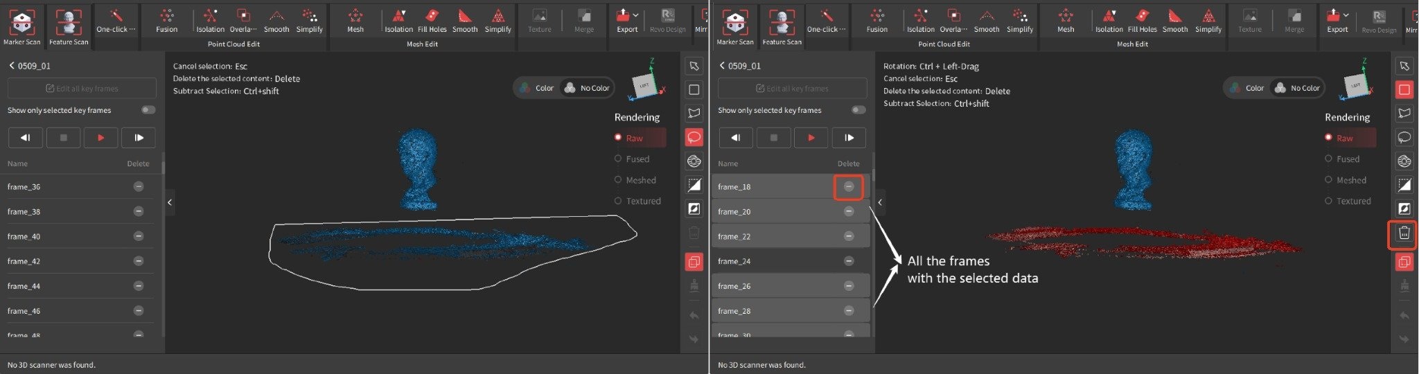
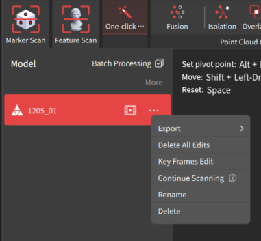
¶ 10.Key Frames Edit
When using Full-field or Auto Turntable Scanning mode, use it to edit or delete the raw data before fusion. This tool can be used to go through captured point cloud data frame-by-frame and quickly find the misaligned or faulty frame for deletion.
 |
Key Frames Edit Tutorial Video (for reference only) Go to the project panel and click the icon or click the icon or click the  icon > Key Frames Edit to enter the Key Frames Edit interface. There are two methods to edit the keyframes: icon > Key Frames Edit to enter the Key Frames Edit interface. There are two methods to edit the keyframes: |
1) Click the  button to autoplay through the frames individually. Then, select any unwanted frames and click the
  button next to each frame's name.
2) Enter the Key Frames Edit interface and use a selection tool from the Tool Bar to select unwanted data. The frames with the data will be automatically selected. Click the  button to delete the unwanted data in the selected frames or the button to delete all selected frames.
¶ 11.Model Display
Enter the project interface, and click "Display" in the menu bar to set how the model is displayed.
• Zoom to Fit
Click to reset the zoom to its original position so the 3D model is fully visible on the screen.
• Default Position
Shows the 3D model from a viewpoint determined by the first few frames captured.
• Perspective View
The camera is positioned at a fixed point in space, so the model has a sense of depth and distance. This is the default view.
• Orthogonal View
All objects appear at the same scale, and all three dimensions (width, height, and depth) are projected onto a 2D plane to preserve their relative sizes and positions.
• Show Bounding Box
Displays or hides the bounding box around the current model. The bounding box is a rectangular box that is wrapped as tightly as possible around the object.
• Show Rotation Ball
Displays the XYZ rotation axis to show the model's orientation in 3D space.
• Show Grid
Displays or hides a virtual 3D grid in the editing interface. The grid is a structure of horizontal and vertical lines that help to position and align objects.
• Show Scanning Location
Displays location references for scans captured in Single-shot mode. Use it to see if any color data needs to be reshot. Click on any reference to view a single frame captured at the current position; double-click on a reference to view the model image captured at the current position.
• Show Reverse Point
Shows or hides the surface across from the current one in another color (brownor transparent).
• Mesh Model Display
Solid: Turn the model's surface on or off.
Wireframe: Shows the model's wireframe.
Wireframe Overlay: Shows the model's wireframe overlay.
• Model Properties
Click Model Properties to change the model's color and surface properties.
• Enable Select Through
Enable it to select data right through the model.
• Screenshots
Full Screen: Capture the entire screen.
Model Only: Only captures an image of the 3D model.
• Light Source
Drag the icon to adjust the Light Source's position. Double-click the icon to reset to the default location. Click off the icon to close.
¶ 12. Model & Project Management
¶ 12.1 Models Management
 |
Batch Processing If you've created a project with multiple scans, batch processing can perform the Fusion or Meshing processes with the same settings on multiple models. Click the batch processing button. Select the models to be processed. Select a setting for Fusion or Mesh and click Apply. Delete All Edits It deletes all the edits and resets the model to being unprocessed raw data. Renaming/Deleting Models Double-click the model on the project pane to rename it or click the |
¶ 12.2 Import Models
Enter the project interface, go to the Menu Bar, click File > Import, find the desired model on your PC, and click Open.
¶ 12.3 Export Models
Method 1: Open a Project > On the project panel, select the wanted model, click the icon > Export, select the state, and select the file destination and format.
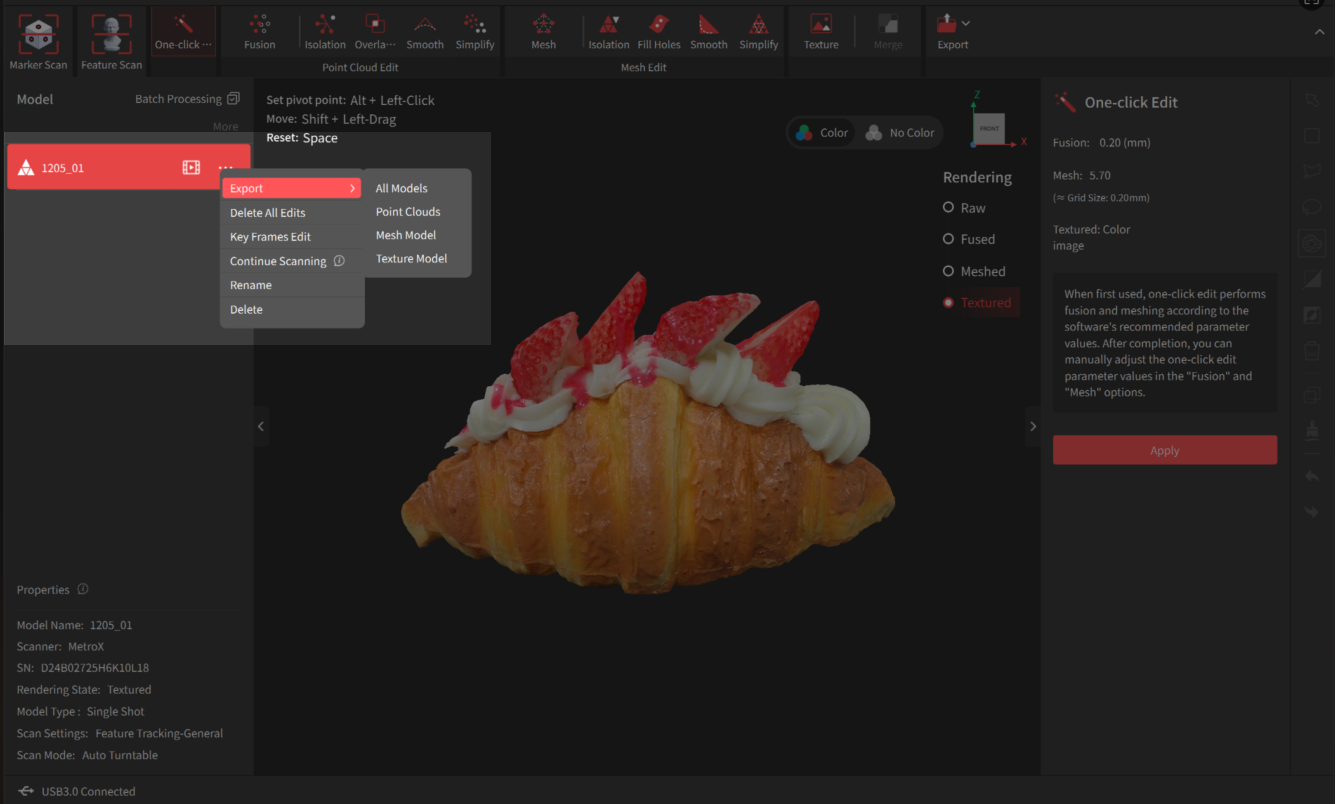
Method 2: Open a Project > On the project panel, select the wanted model. Click Export in the Tab Bar and select the state, origin types and file format. Then save it on your PC.
Model Origin: The coordinate origin is set at the center of the front surface of the scanned object's bounding box.
Original Origin: The coordinate origin is the left camera after epipolar rectification of the scanner, or the coordinate origin of the imported global marker.
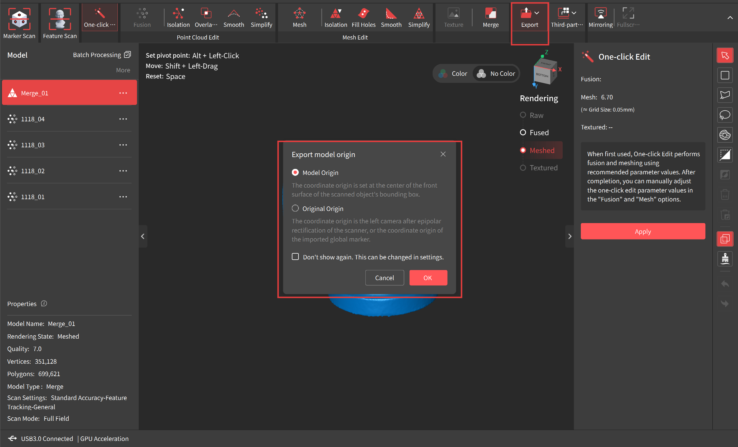
Note: Selectable file formats depend on the model state being exported.
¶ 12.4 Project Management
There are three methods of creating new projects:
• On the Homepage (connected scanner) > Click the New Project pane or Scanner Connection Status pane.
• Click the  button between the Home and Open Project buttons in the Menu Bar.
• In the Project interface, go to Menu Bar and click File > New Project.
Opening a Project
There are two methods of opening a project:
• On the Homepages' project list > Double-click a project.
• In the project interface, go to Menu Bar, and click File > Open a Project or Open Recent Projects.
Opening Folder
In the project interface, go to the Menu Bar, and click File > Open Folder to open the folder where the current model is located.
Saving Projects
When a project is open, go to Menu Bar and click File > Save.
Renaming Projects
On the Homepages' project list > Click the icon on the project's thumbnail > Click Rename.
Deleting Projects
• Deleting Individual Projects
On the Homepages' project list > Click the icon on the project's thumbnail > Click Delete.
• Deleting Multiple Projects
On the Homepages'project list > Click the tick box next to one or more project thumbnails > Click Delete.
¶ 13. Help & Feedback
¶ 13.1 Online Support


¶ 13.2 Feedback
Please submit your feedback if you have any problems when using our products or software.
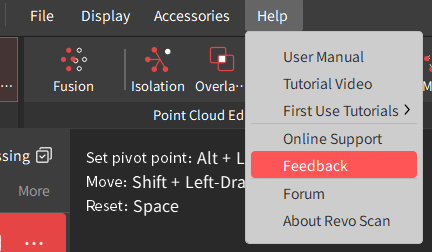 |
In the project interface, go to Menu Bar and click Help > Feedback to access the feedback page. |
¶ 13.3 Social Media
Please submit your feedback if you have any problems when using our products or software.
 |
Scan the QR code to learn about Revopoint's official social media accounts. |