¶ 1. About This Manual
Welcome to your Revopoint 3D scanner user manual! This manual provides Trackit's operation guide and instructions. Please read the manual before using the scanner for the first time to ensure you use it correctly and safely. If needed, you can click on any topic in the navigation bar to quickly jump to that section.
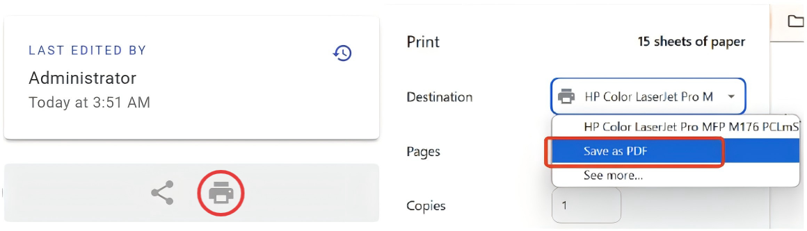
Manual Download
If you need a PDF manual, click the Print Format button at the bottom of the navigation bar on the left side of the manual, and select "Save as PDF" from the options.
¶ 1.1 Read Before Using
- This manual is specifically for the Trackit Optical Tracking 3D Scanner.
- This manual is frequently updated to reflect the latest features and improvements of the product.
- Verify that all components in your box are complete and undamaged before first use.
¶ 1.2 Warnings
- This product uses a Class 1 laser projector. Avoid looking directly at it at close range! Please refer to the Class 1 laser standard document for details. To prevent laser reflection, avoid placing reflective surfaces like mirrors or glass in the path of the laser beam.
- Please keep the product away from water and other liquids. Use the product in a dry and dust-free environment.
- To ensure accuracy, please use the product in accordance with the following environmental requirements:
- Don't disassemble the product or its components.
- Be sure to place the product and accessories in the case when transporting them. It's recommended that all unused products and accessories be stored in their case.
① Temperature: 20-25°C
② Humidity: 30-60%
③ Airflow: Avoid air turbulence, such as from air conditioning vents, fans, or strong convective air currents.
④ Vibration: Avoid vibrations caused by activities such as frequent jumping, walking, or heavy objects falling.
¶ 1.3 Online Resources


¶ 2. About Trackit
¶ 2.1 What's in the Box

Trackit Unboxing Tutorial Video
¶ 2.2 In-box Layout
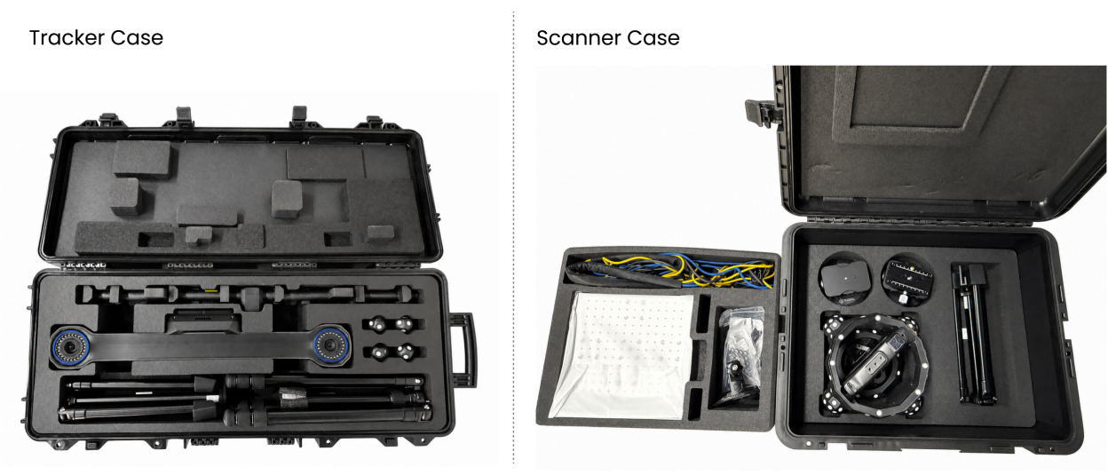
Trackit Packing Tutorial Video
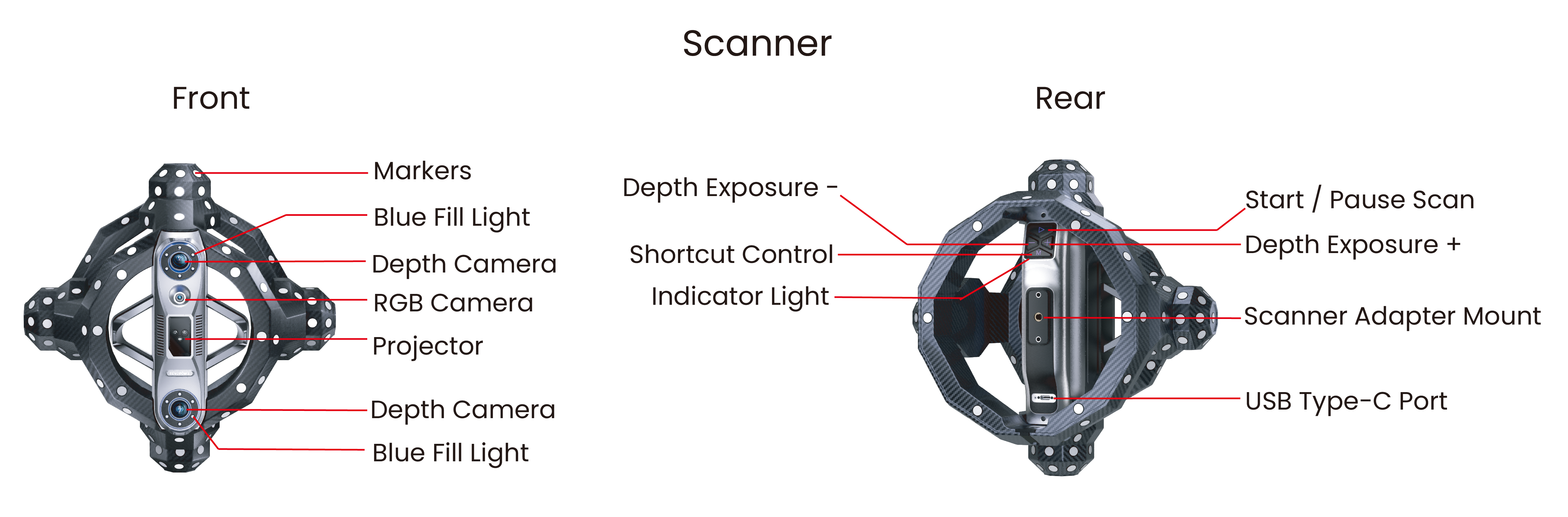
¶ 2.3 Product Profile
¶ 3. Software Download & Installation
¶ 4. About Revo Track Software
¶ 4.1 Interface Overview
¶ 4.2 Settings
¶ 4.3 Software Functions
¶ 5. Calibration
Be sure to calibrate your Trackit before your first use, after scanning environment/temperature changes, or after transportation.
It's recommended to calibrate your Trackit after one week of use or when a high-accuracy scan is required.
Trackit Calibration Tutorial Video
¶ 5.1 Precautions
Note: When performing ground calibration, adjust all three legs of the Tracker tripod to the shortest length, and set the angle of each leg to the third level, 80°. Then, adjust the central column to a proper height to ensure that the Tracker aligns with the designated position.
¶ 5.2 Scanner Calibration
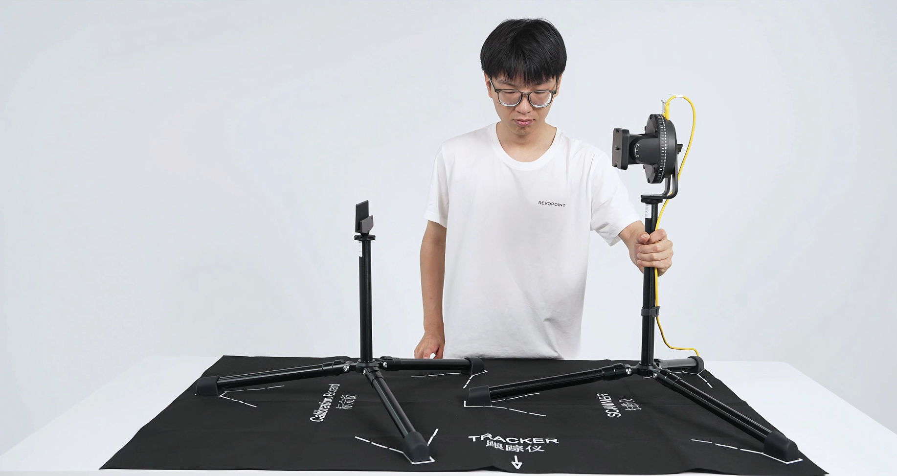
1) Set up Tracker's Tripod
Step 1: Pull the legs outwards to unfold the tripod.
Step 2: Continue pulling the legs down until they lock into place. (A click sound indicates it has locked into one of the three preset positions shown in descending order.)
Step 3: Adjust the center column and the legs to your required height as shown in the diagram.
Note: If you need a wider leg spread, follow the operation in the video.
2) Install Tracker
Step 1: Align the Tracker Gimbal’s screw hole with the tripod screw, then rotate the gimbal until securely attached to the tripod.
Step 2: Slide the Quick Release Plate at the bottom of the Tracker into the groove of the Quick Release Clamp while ensuring that the central white lines are aligned. Then, tighten the locking knob clockwise.
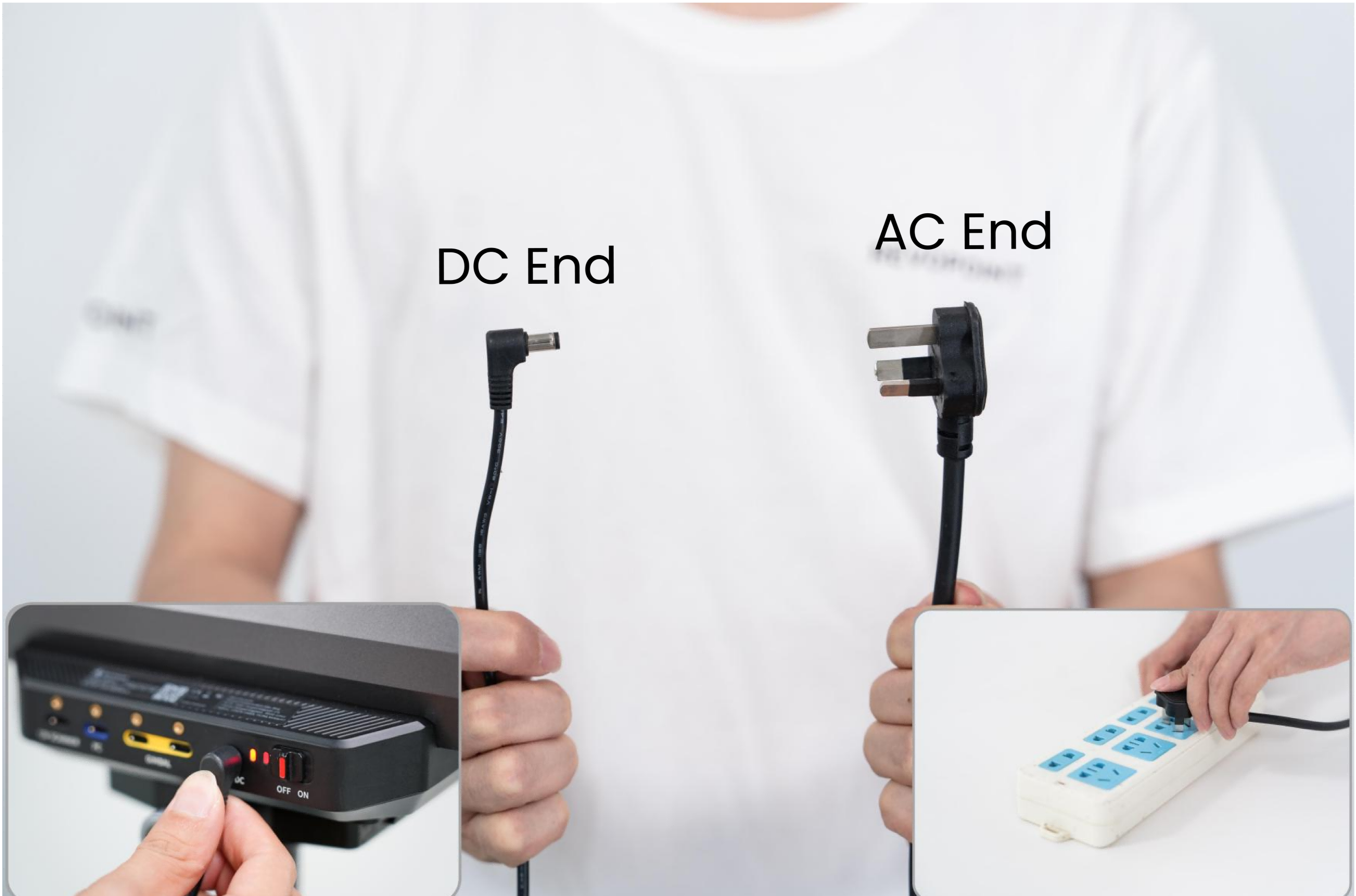
3) Connect Tracker
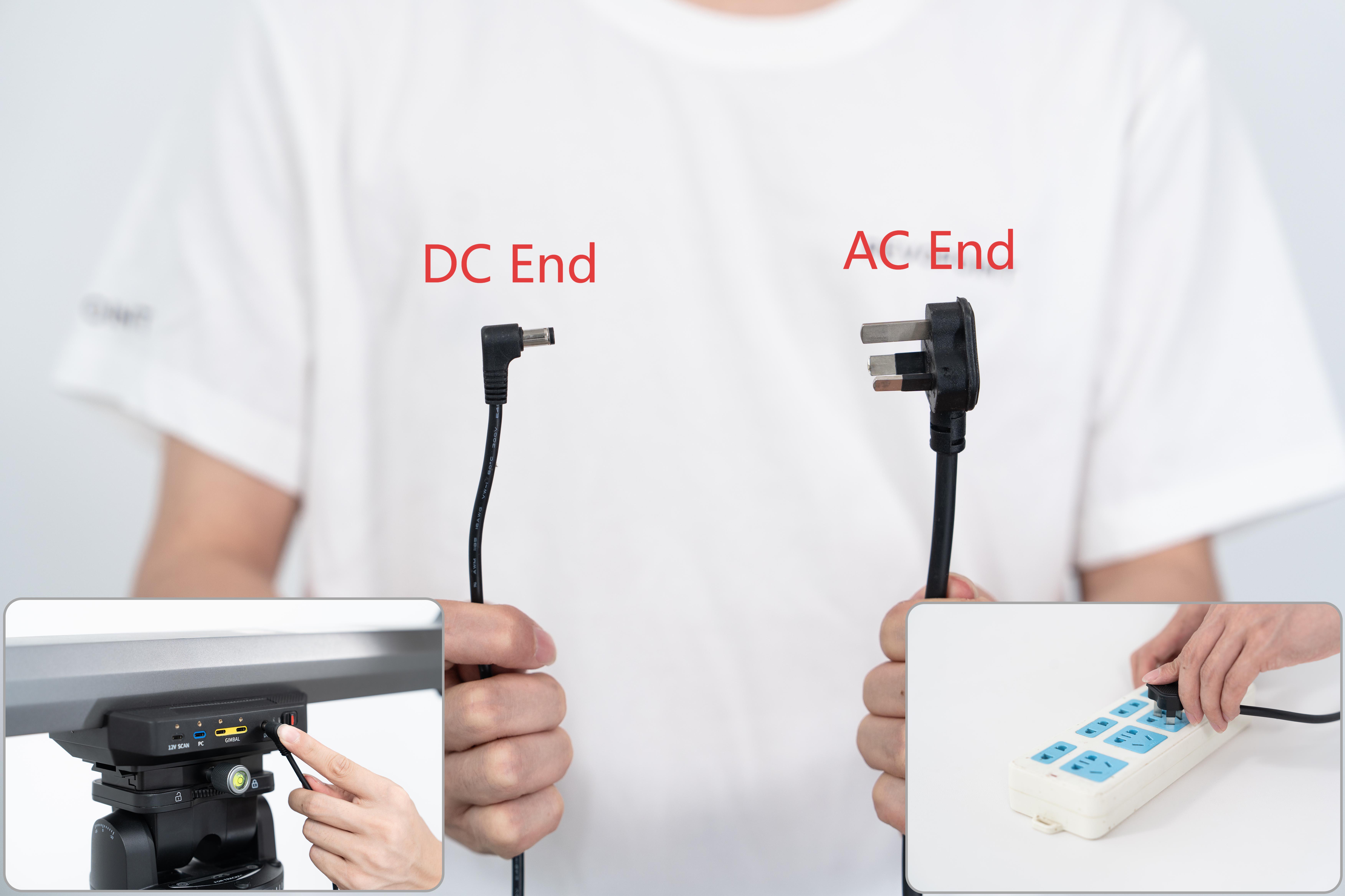
Step 1: Connect the Power Adapter’s DC end to Tracker’s “12V DC” port, and AC end to a power supply.
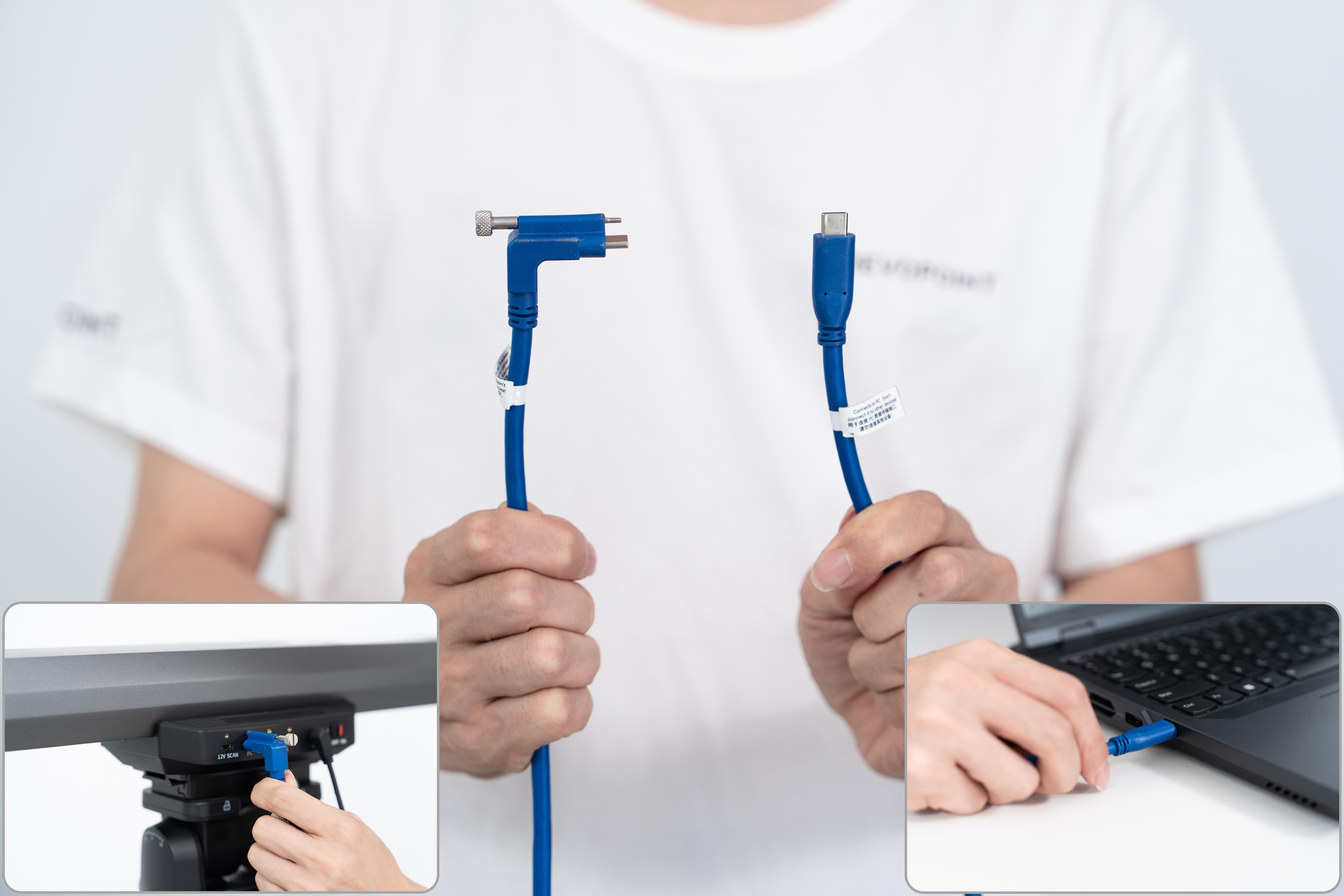
Step 2: Connect the PC Cable’s L-shaped end to Tracker’s “PC” port and tighten the screws. Insert the straight end into a USB Type-C port on your PC.
4) Connect 5.3Scanner
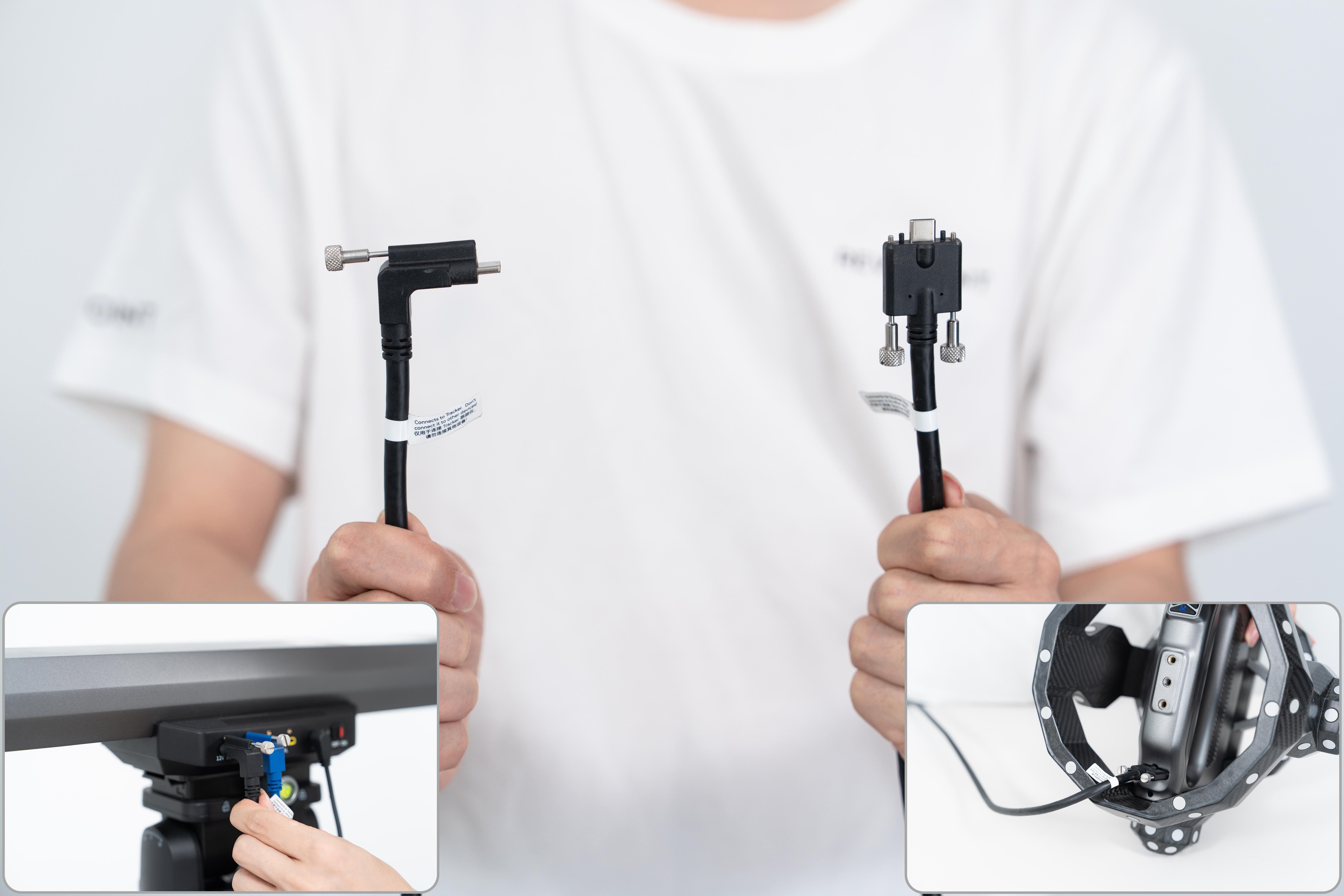
Connect the Scanner Cable’s L-shaped end to Tracker’s “12V SCANNER” port and tighten the screws. Connect the straight end to the USB Type-C port on the Scanner and tighten the screws.
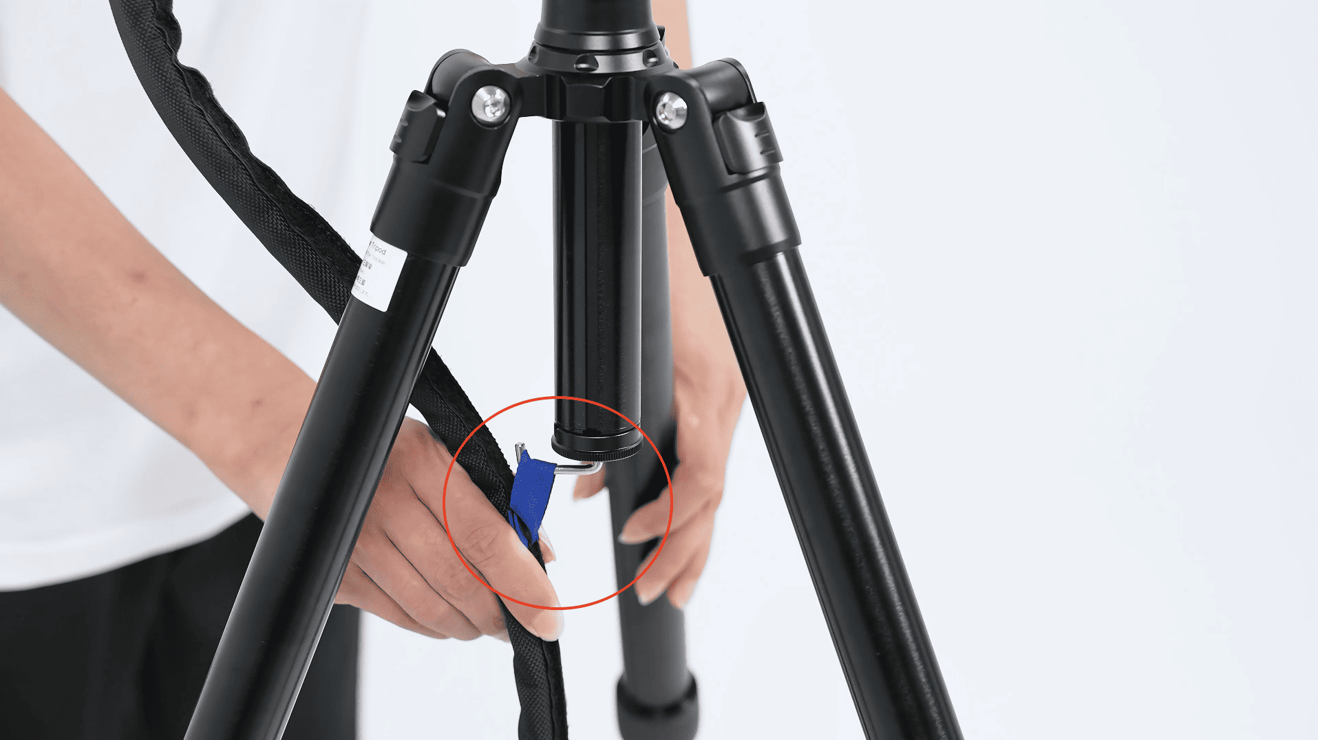
Attach the hanging loop on the cable sleeve to the hook at the bottom of the Tracker Tripod's central column.
5) Secure the Cables
Secure all the cables to the floor near the Tracker's tripod base using the Suction Cup Cable Holder to prevent any movement that could affect accuracy.
6) Power Trackit
Turn on the power switch on the Tracker’s back. When the right LED turns green and the software interface shows Scanner and Tracker connected, it’s ready.
7) Enter the Calibration Program
Open the software, and click the "Scanner Calibration" in the bottom left corner to enter the calibration program.
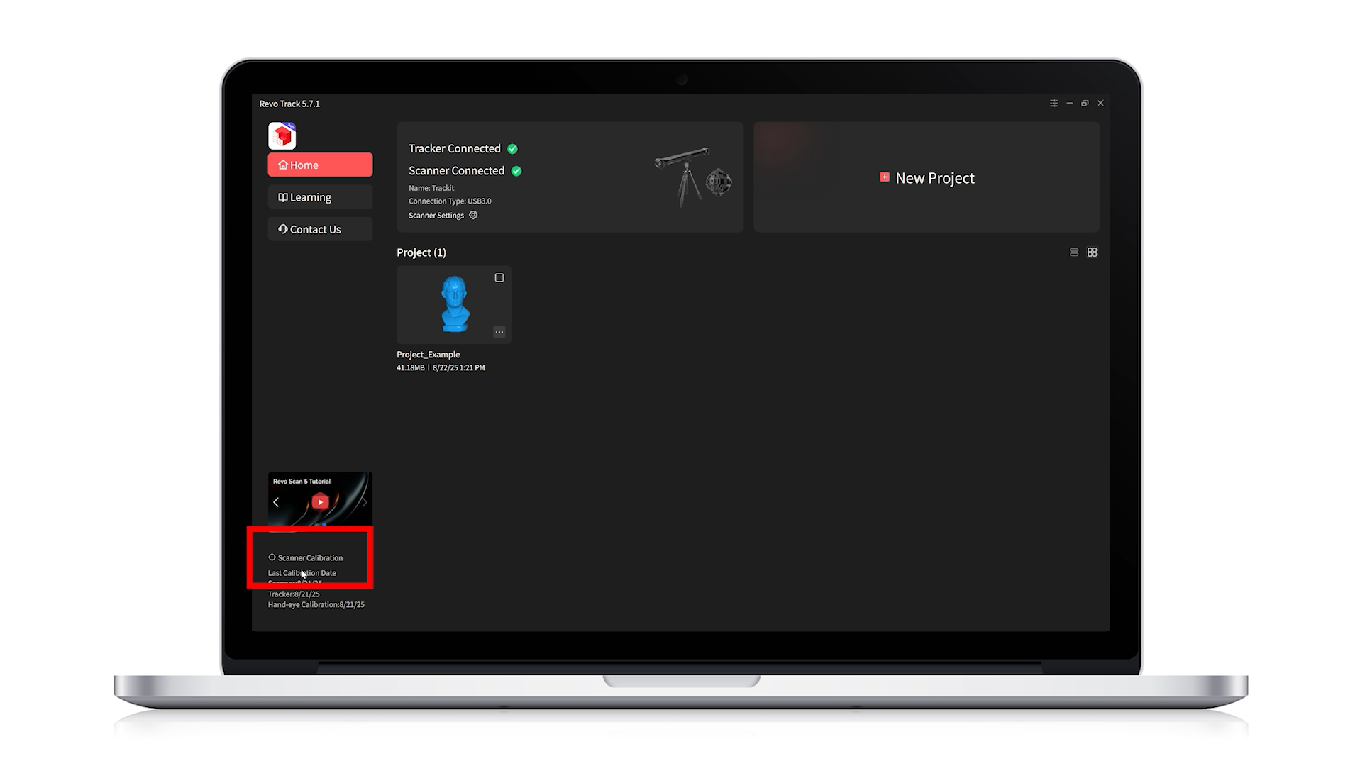
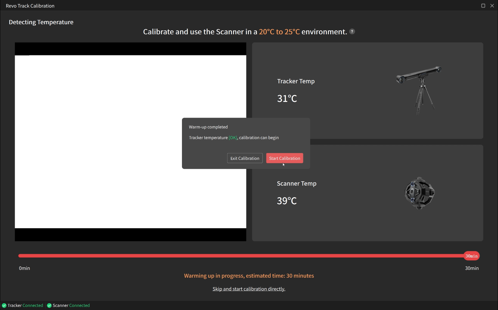
For the initial calibration, it is recommended to perform Full Calibration. After entering the calibration process, the software will automatically detect the temperature of both the Tracker and Scanner.
- If Tracker's temperature is too high, adjust the operating temperature and try again;
- If Tracker's temperature is normal or too low, the software will automatically preheat the Tracker.
For best accuracy, wait until preheating is complete and the Tracker has reached the proper operating temperature before starting calibration. Then, follow the steps below to proceed with the Scanner Calibration.
8) Import SN Info
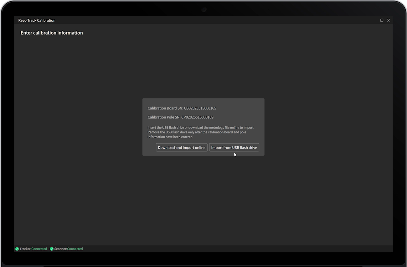
For the initial calibration, follow the on-screen prompts to insert the USB Flash Drive into your PC.
.png)
Then, scan the QR codes on the Calibration Pole and the Calibration Board.
Note:The USB Flash Drive is preset with the name "Revopoint." Do not rename it, as this may cause import errors.
.png)
Select "Download and Import Online" or "Import from USB Flash Drive" to import their SN info.
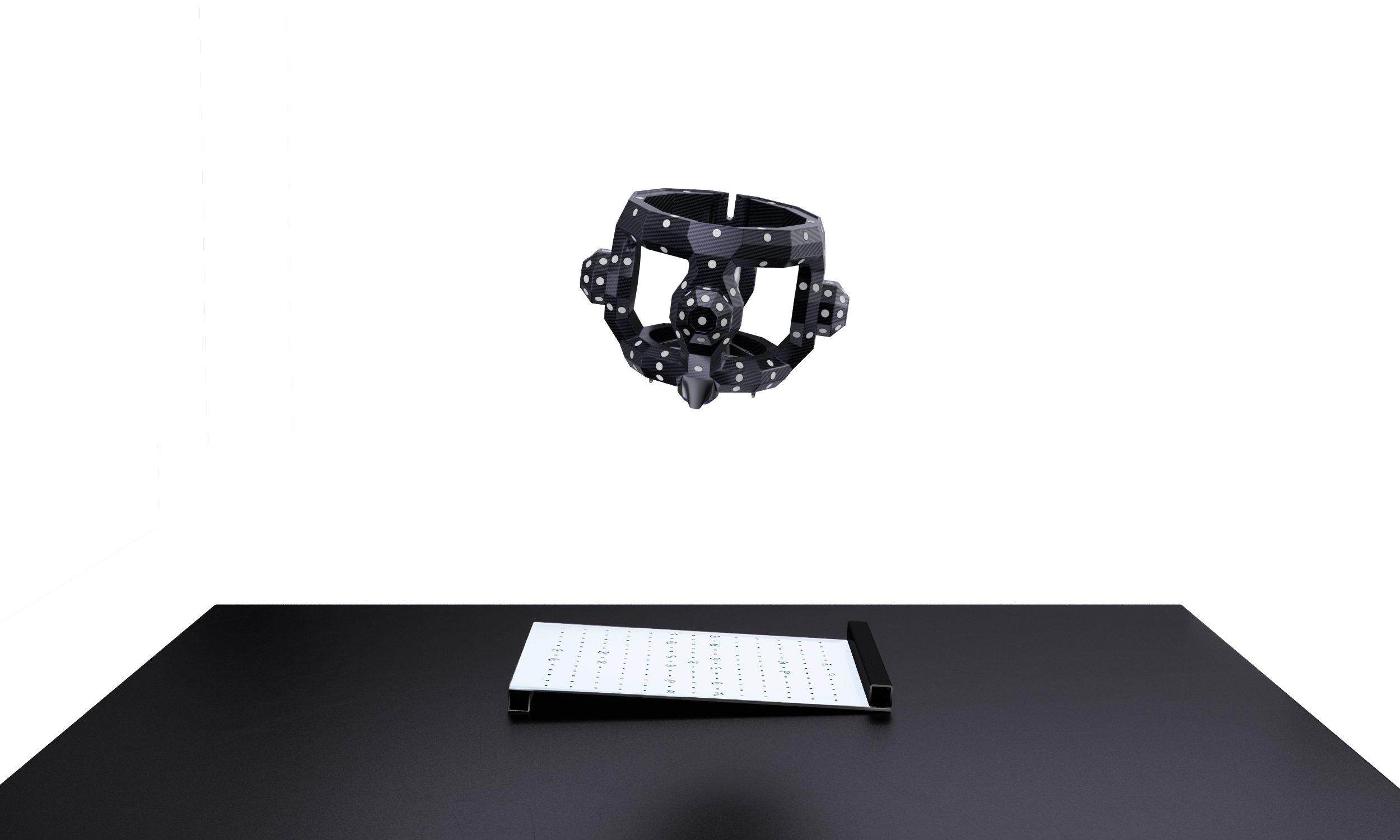
9) Scanner Accuracy Check
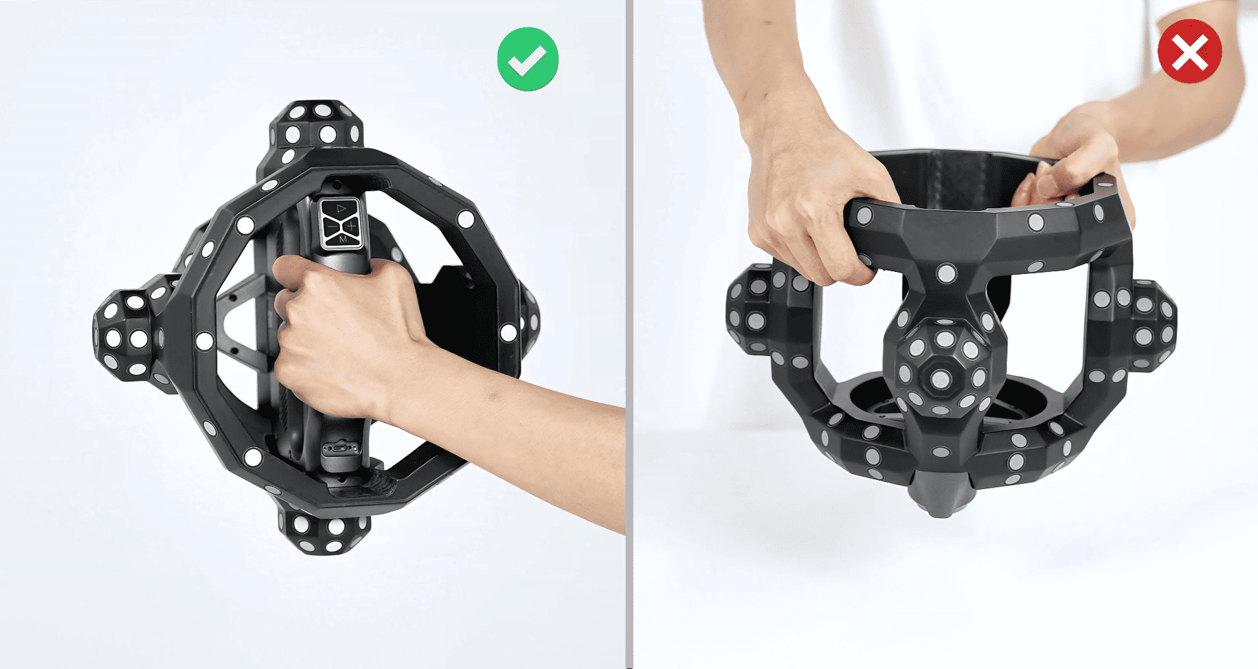
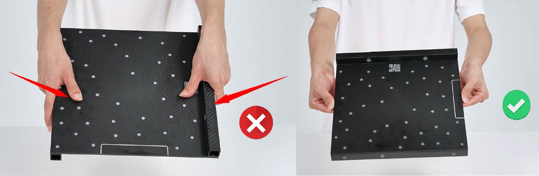
Place the Calibration Board flat on a table with the white side facing up. Hold the Scanner, and follow the on-screen prompts for Scanner accuracy check. If accuracy check is not qualified, click "Start Calibration" to calibrate.
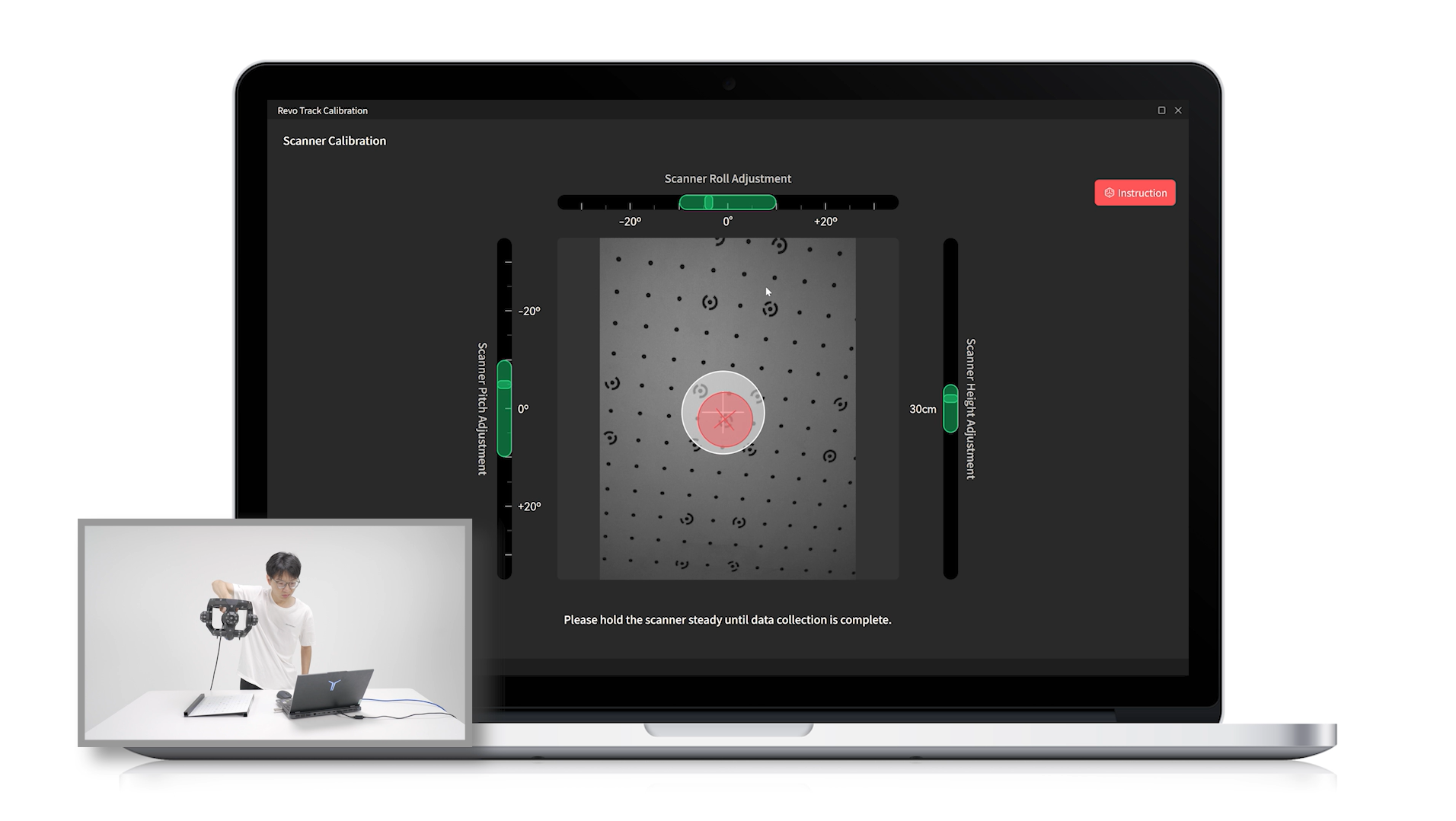
10) Start Scanner Calibration
Calibrate the Scanner at different heights and directions according to software prompts.
After Scanner calibration, the software calculates the results. If qualified, click "Continue" to proceed to the Tracker accuracy check and calibration.
¶ 5.3 Tracker Calibration
11) Tracker Accuracy Check
Step 1: Hold the calibration pole horizontally, stand 2 meters from the Tracker, and align the side with the markers directly towards the Tracker. According to the interface prompts, adjust the calibration pole to the designated position to complete the horizontal accuracy check.
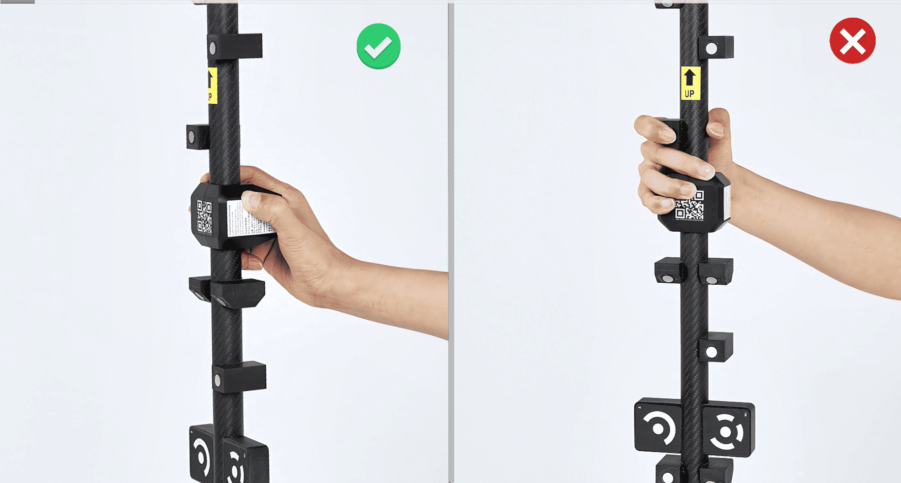
Step 2: Hold the calibration pole vertically about 2 meters from the Tracker, align the side with the markers towards the Tracker, ensure the inclined side faces downward, and the "up" arrow points upward. According to the interface prompts, adjust the calibration pole to the designated position to complete the vertical accuracy check.
Step 3: Hold the calibration pole vertically, tilt it 45° backward, and position it about 2 meters from the Tracker with the side with markers facing it. Ensure the inclined part faces downward and the "up" arrow points upward. Follow the interface prompts to adjust the calibration pole to the specified position. Afterward, perform the accuracy check at the 45° angle.
After the accuracy check, decide if Tracker calibration is needed based on the results. If needed, follow the steps below to perform Tracker Calibration.
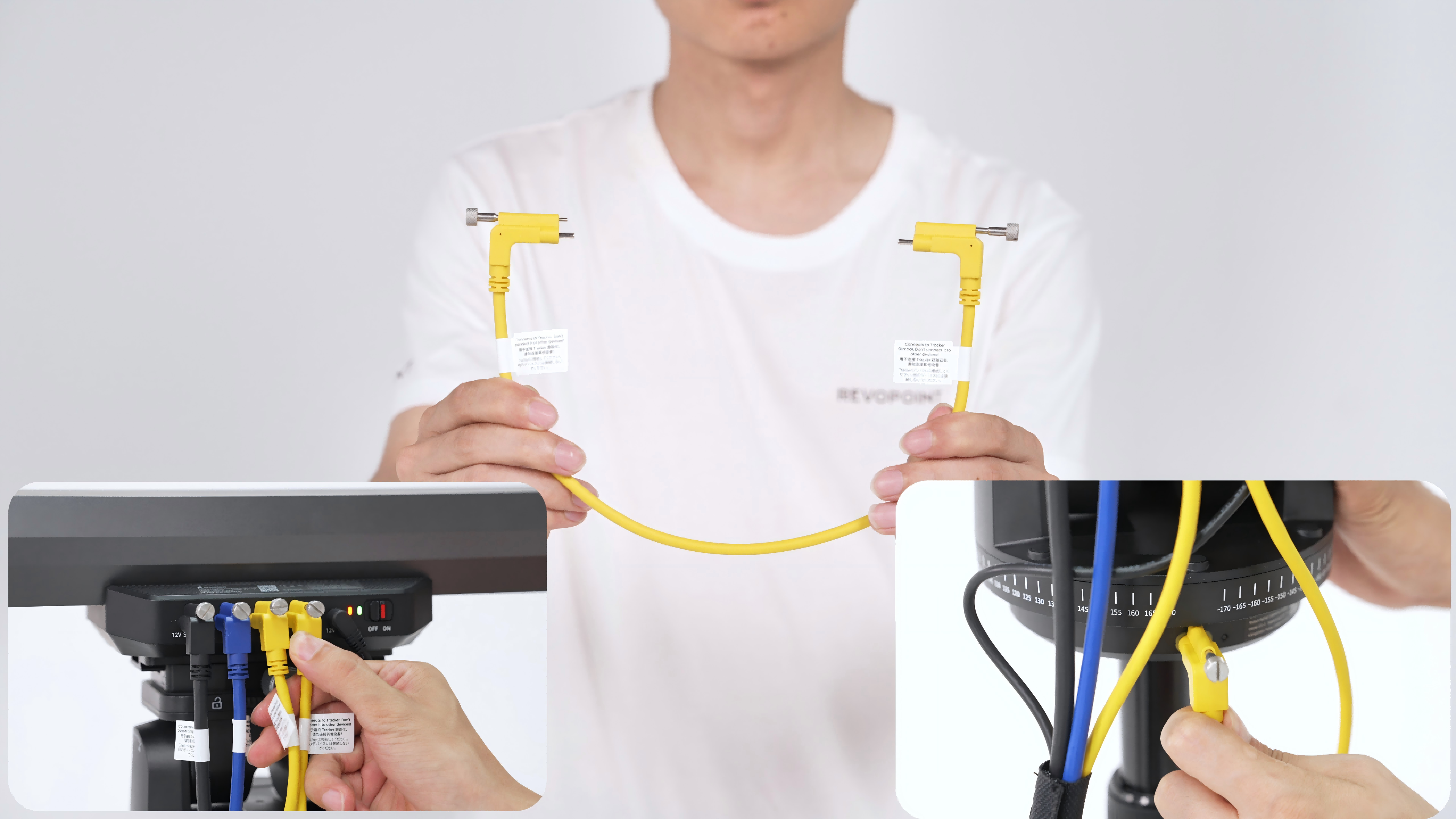
2) Connect Tracker Gimbal
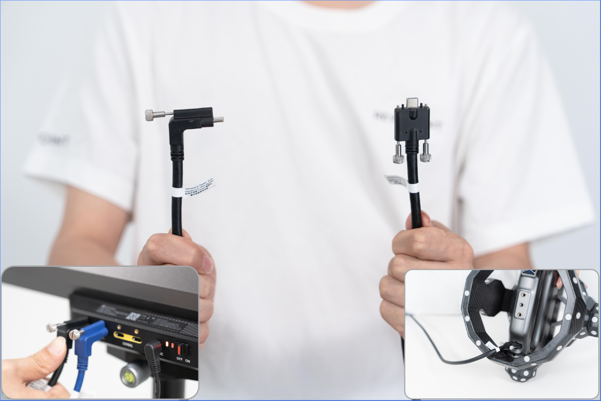
Connect the Tracker Gimbal Cable to Tracker’s "Gimbal" port and the gimbal's port. Then, tighten the screws.
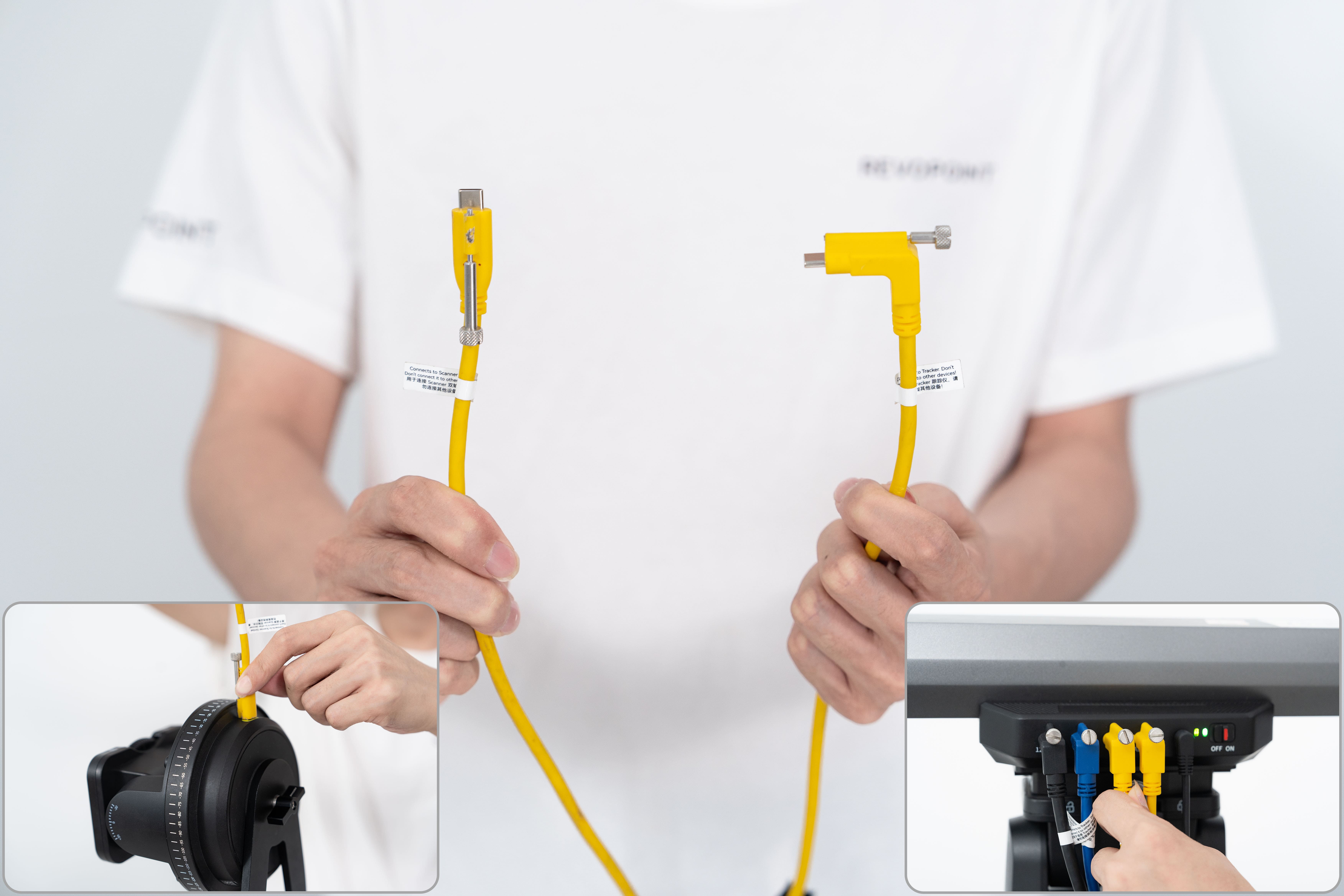
3) Install and Connect Scanner Gimbal
Step 1: Install the Scanner Gimbal onto the Scanner Tripod with its bolt.The Scanner tripod's legs have only one standard angle. Please ensure that all legs are set to this angle during use.
Step 2: Connect the Scanner Gimbal Cable’s L-shaped end to Tracker’s "Gimbal" port and tighten the screws. Connect straight end to the gimbal's port and tighten the screws.
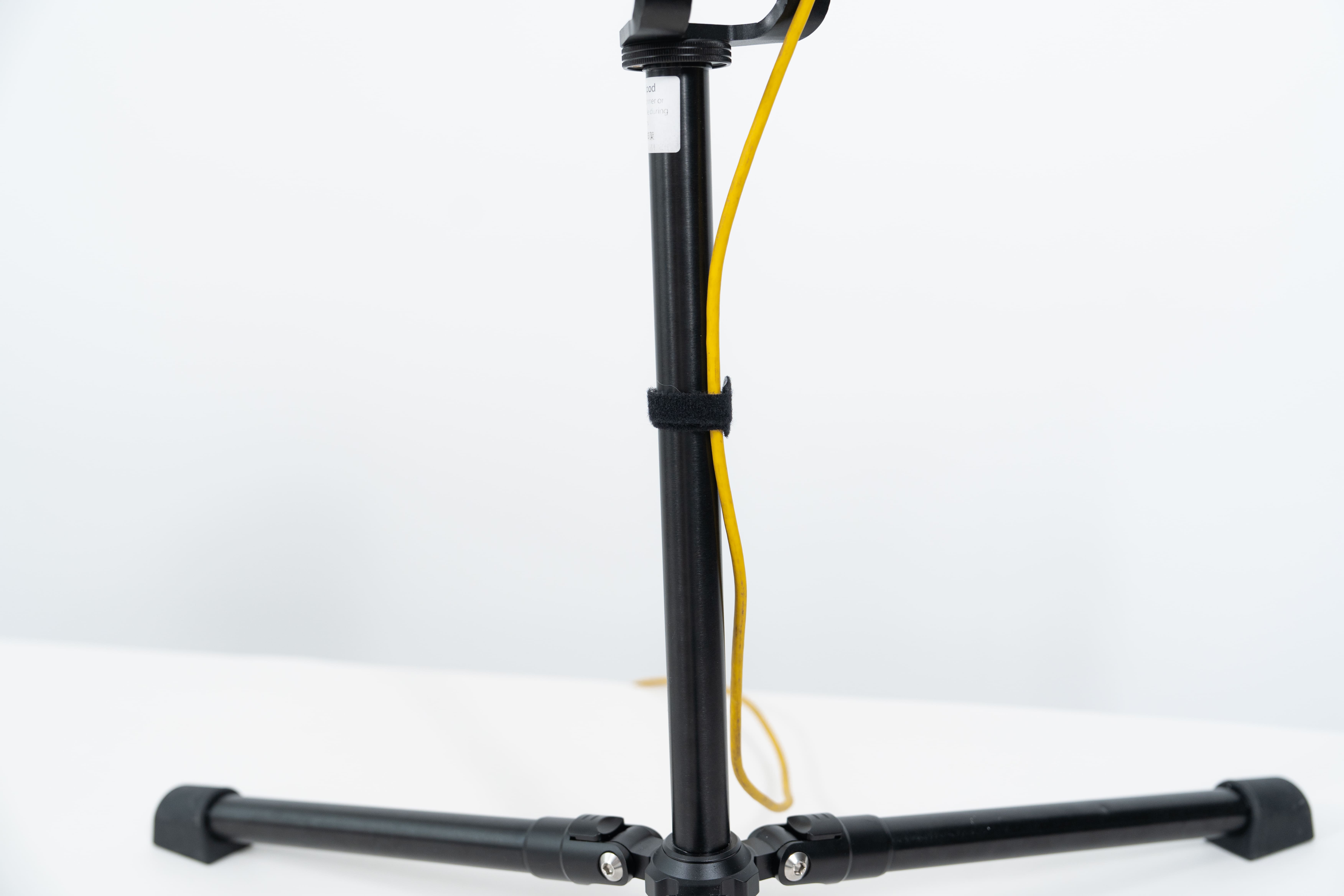
Attach the cable to the Scanner Tripod using cable ties to prevent tangling with the Calibration Pole during calibration.
4) Install the Calibration Pole
Keep the Calibration Pole upright with the inclined surfaces facing the table. Mount the Calibration Pole onto the Scanner Gimbal. Then, slide the latch until the screws are tightened.
5) Start Tracker Calibration
Position the Scanner Tripod with the Calibration Pole facing the Tracker. Adjust the Tracker Tripod’s height and ensure that all the legs are at the same angle. Then, follow the software prompts to calibrate the Tracker at different distances.
Note: When performing Tracker and hand-eye calibrations, ensure that the Tracker Tripod's legs are adjusted to the minimum angle and extended to their full length. Then, adjust the tripod's height using its central column.
During the Tracker calibration process, do not cover the Tracker's cameras and make sure only the markers on the calibration Pole are within the Tracker's field of view.
¶ 5.4 Hand-Eye Calibration
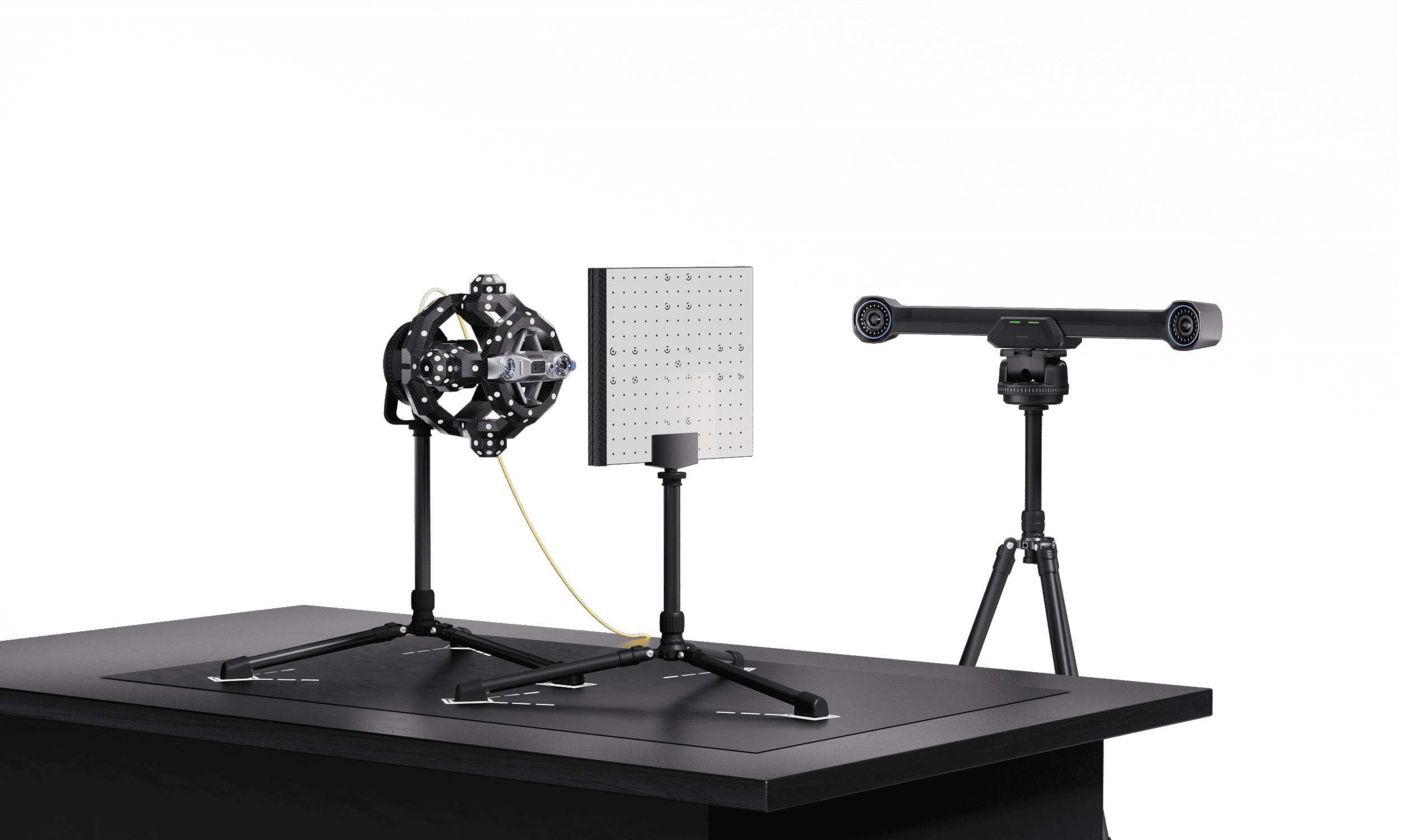
1) Place the Positioning Pad
Unfold the Positioning Pad on a table. Position the Scanner Tripods and Calibration Board Tripods as shown on the Positioning Pad. The two Tripods' legs have only one standard angle. Please ensure that all legs are set to this angle during use.
2) Install the Scanner
Connect the Scanner to the gimbal using the Scanner Adapter. Then, slide the latch until the screws are tightened.
Note: When installing the Scanner, ensure its cable port faces the Tracker.
3) Install the Calibration Board
Place the Calibration Board into its tripod within the white outline, with the black side facing the Scanner and the markers side facing the Tracker.
Note: Ensure no markers are blocked during the placement.
4) Start Hand-eye Calibration
Place the Tracker facing the two tripods and do the hand-eye calibration according to the on-screen prompts in the software.
Note: During the hand-eye calibration process, avoid blocking the Tracker's camera and ensure that only the Scanner and the markers on the Calibration Board are in the Tracker's line of sight.
¶ 6. Scan Setup
¶ 6.1 Precautions
¶ 6.2 Set up Tracker's Tripod
Step 1: Pull the legs outwards to unfold the tripod.
Step 2: Continue pulling the legs down until they lock into place. (A click sound indicates it has locked into one of the three preset positions shown in descending order.)
Step 3: Adjust the center column and the legs to your required height as shown in the diagram.
Note: If you need a wider leg spread, follow the operation in the video.
¶ 6.3 Install Tracker
Step 1: Slide the latch on the Tracker’s gimbal in the direction of the unlocking icon to remove the Quick Release Clamp.
Step 2: Align the central screw hole on the Quick Release Clamp with the screw on the Tracker Tripod. Then, rotate the Quick Release Clamp until it’s securely attached.
Step 3: Slide the Quick Release Plate at the bottom of the Tracker into the groove of the Quick Release Clamp while ensuring that the central white lines are aligned. Then, tighten the locking knob clockwise.
¶ 6.4 Connect Tracker
Step 1: Connect the Power Adapter’s DC end to Tracker’s “12V DC” port, and AC end to a power supply.
Step 2: Connect the PC Cable’s L-shaped end to Tracker’s “PC” port and tighten the screws. Insert the straight end into a USB Type-C port on your PC.
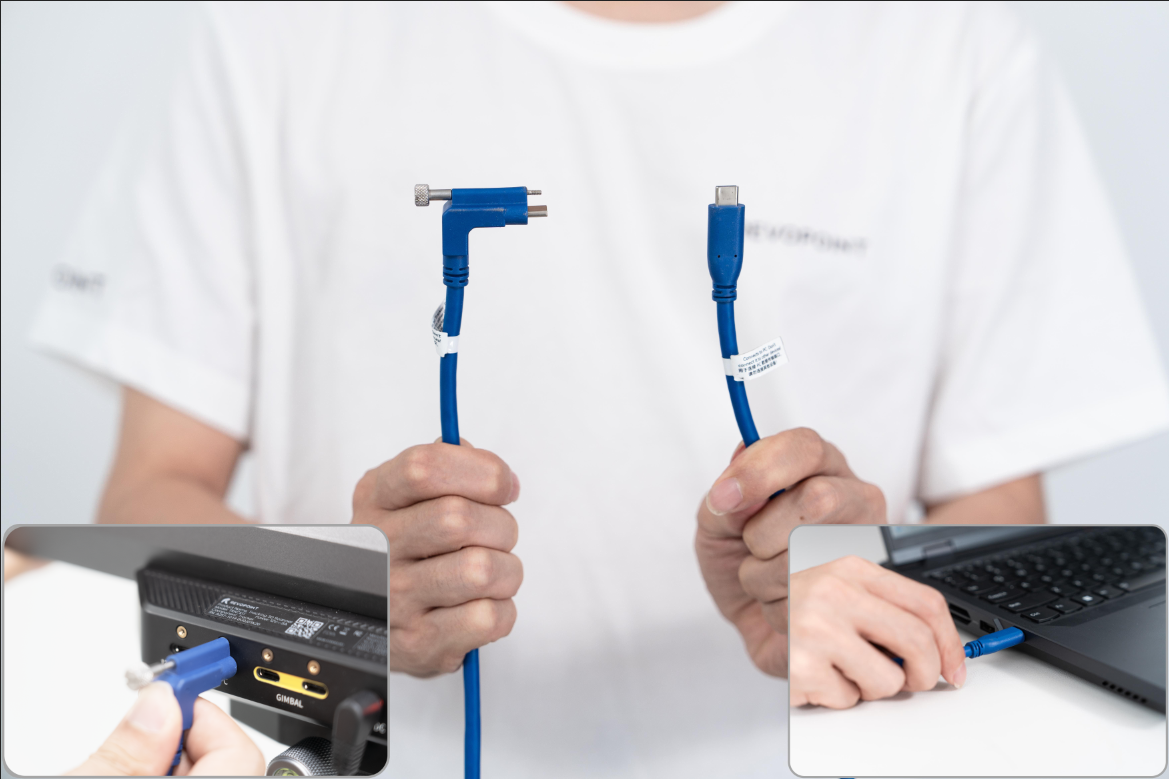
¶ 6.5 Connect Scanner
Connect the Scanner Cable’s L-shaped end to Tracker’s “12V SCANNER” port and tighten the screws. Connect the straight end to the USB Type-C port on the Scanner and tighten the screws.
Attach the hanging loop on the cable sleeve to the hook at the bottom of the Tracker Tripod's central column.
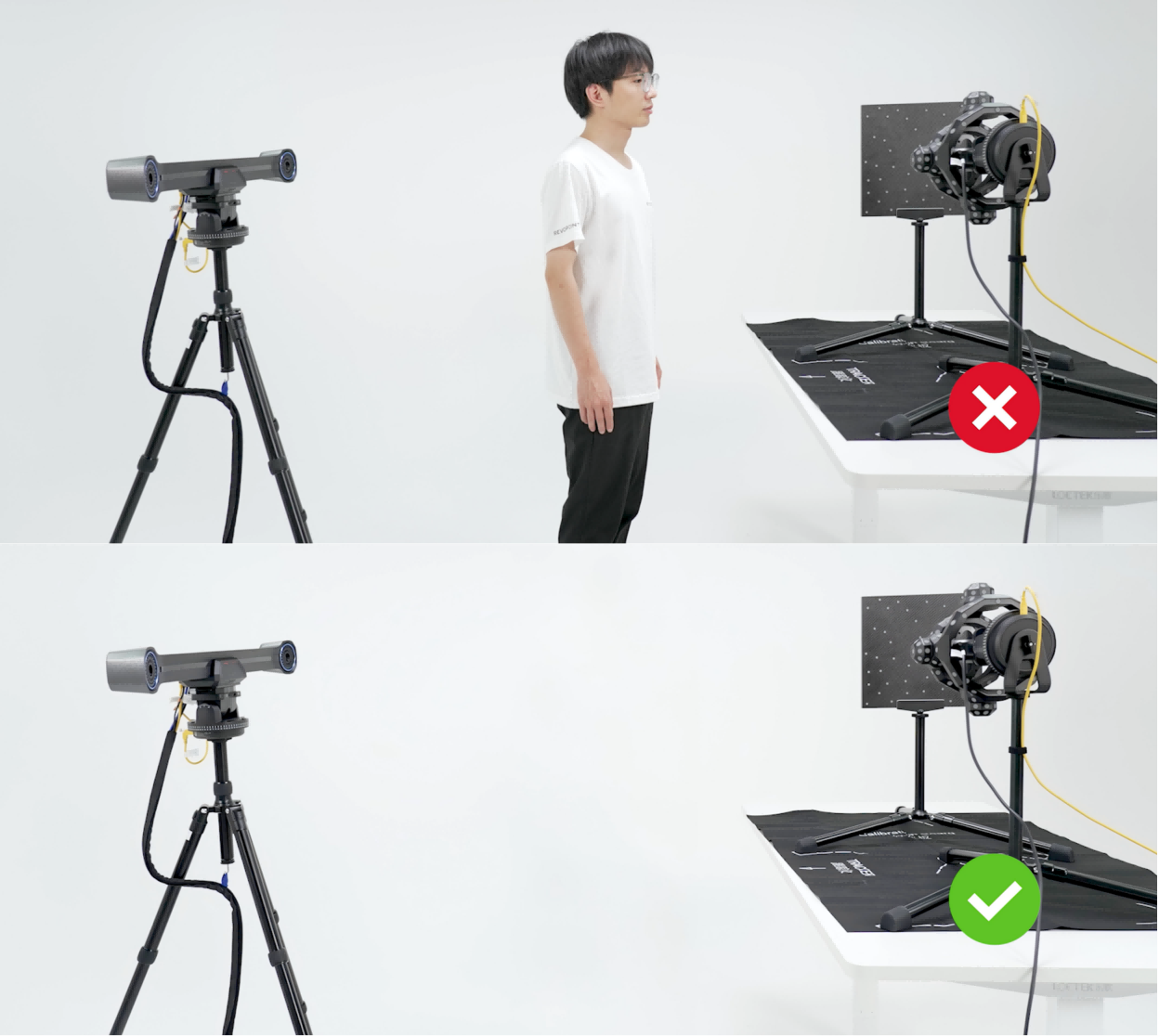
¶ 6.6 Secure the Cables
Secure all the cables to the floor near the Tracker's tripod base using the Suction Cup Cable Holder to prevent any movement that could affect accuracy.
¶ 6.7 Power Trackit
Turn on the power switch on the Tracker’s back. When the right LED turns green and the software interface shows Scanner and Tracker connected, it’s ready.
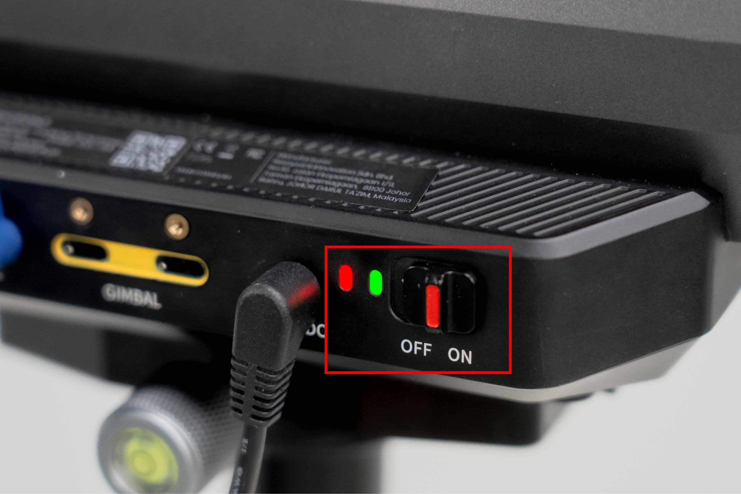
Troubleshooting:
If there is a connection failure or the device does not work, unplug the straight end of the PC cable from the computer. Then, turn the power switch on the back of the Tracker off and on until the right LED turns green. After that, reconnect the straight end of the PC cable to your PC.
It's recommended to repeat the operation several times to resolve the problem. If it doesn't work, contact our customer service team for assistance.
¶ 6.8 Connection for Standalone Use of Scanner
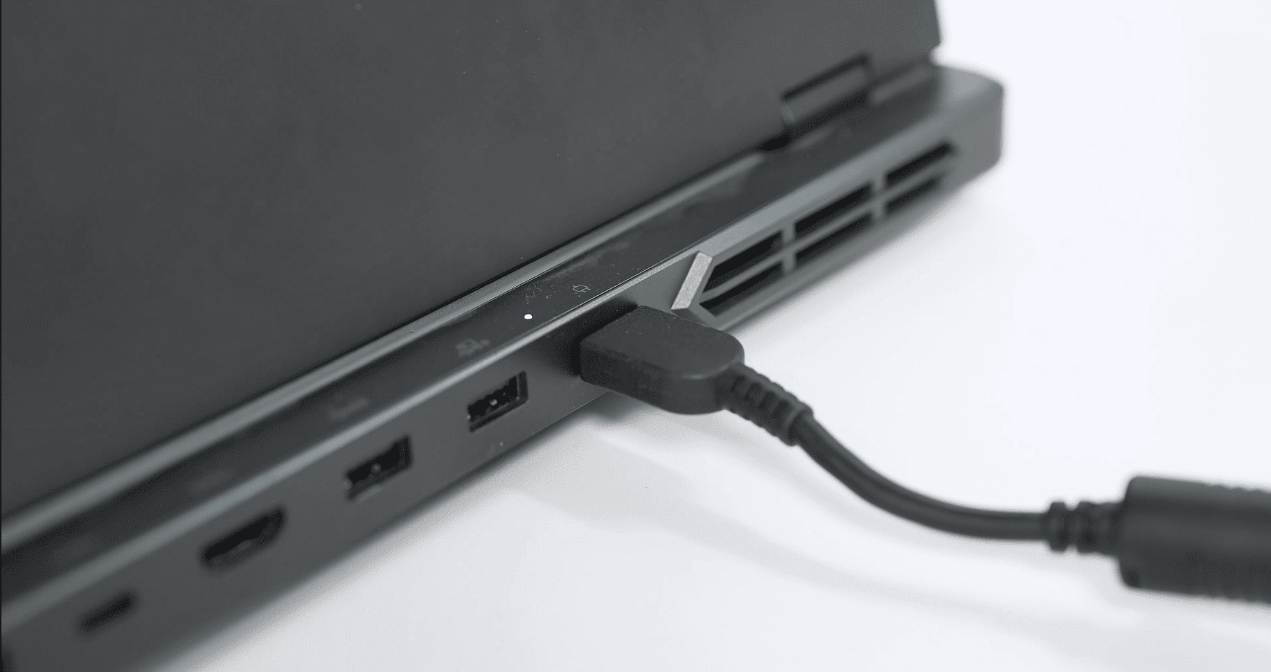
When using the Scanner independently, the Scanner PC Cable connects it to a computer and power source, enabling quick Marker Scan without the need to set up a complex Tracker environment.
Follow steps ① - ④ in the diagram to connect the Scanner to a PC and power source. The cable is optional and available for purchase at the official Revopoint online store.
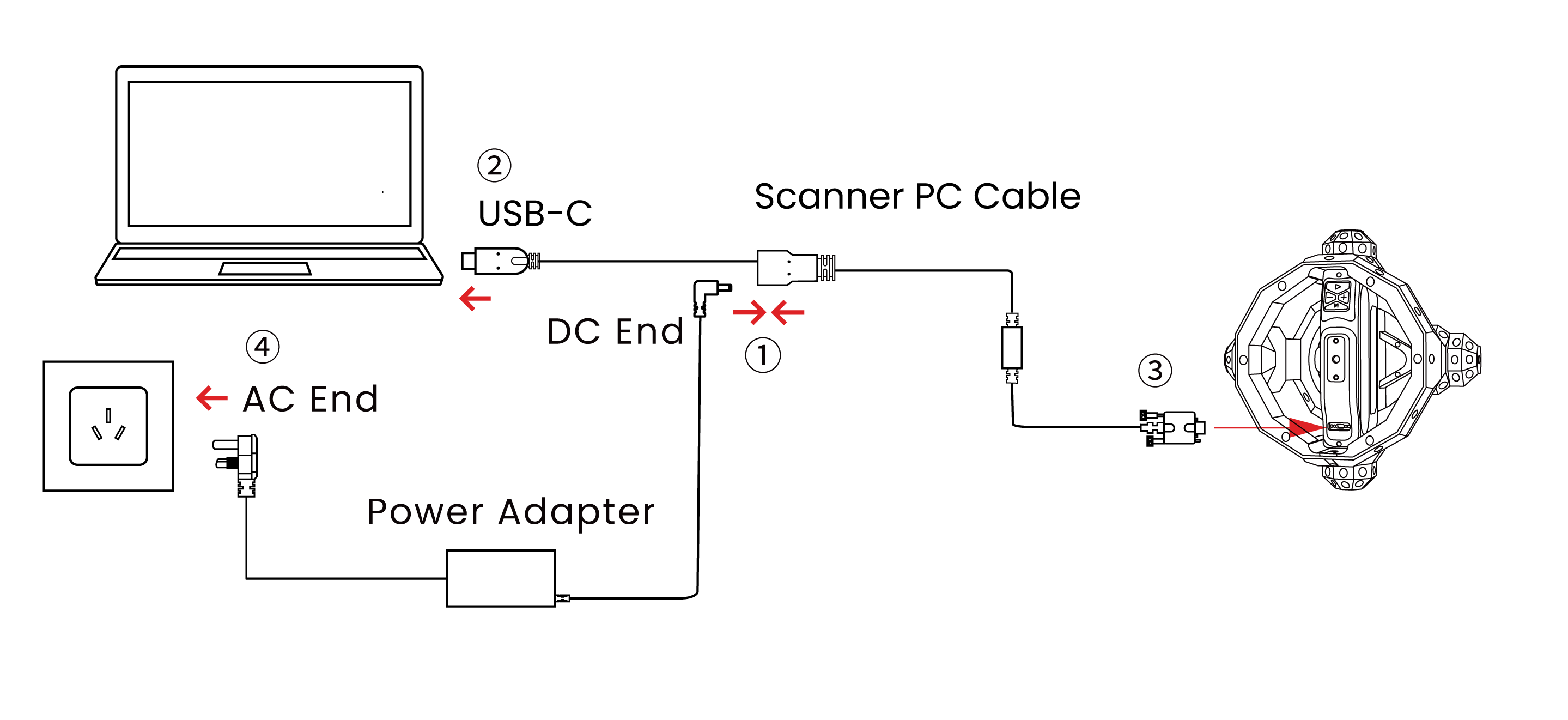
Note:
The cable must be used with the Power Adapter provided in the Trackit case.
The software defaults to Marker Scan mode when using this cable.
This cable is intended for standalone use of the Scanner only. To perform Track Scan or Multi-position Scan with the Tracker, make sure to connect the Scanner to the Tracker as shown in the previous sections.